| Heart of Avalonia |
Frost-heaved Bedrock: Illustrative Feature 06
Bedrock disruption by subglacial ice segregation. Cold deglaciation.
Isthmus of Avalon
Bedrock disruption by subglacial ice segregation. Cold deglaciation.
Isthmus of Avalon
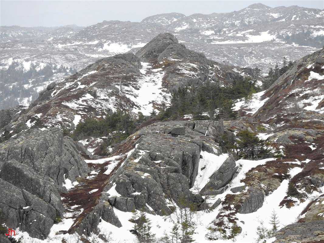
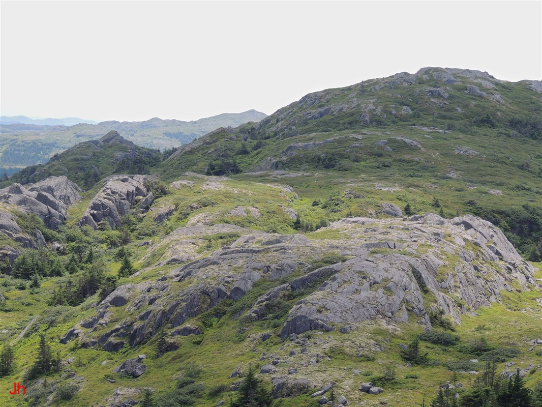
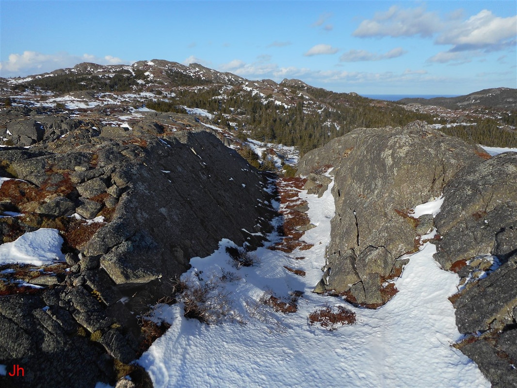
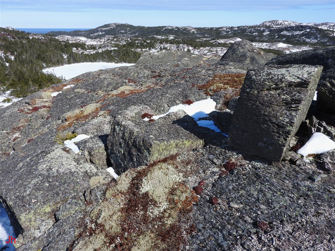
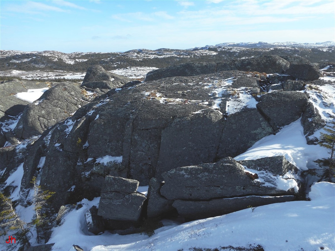
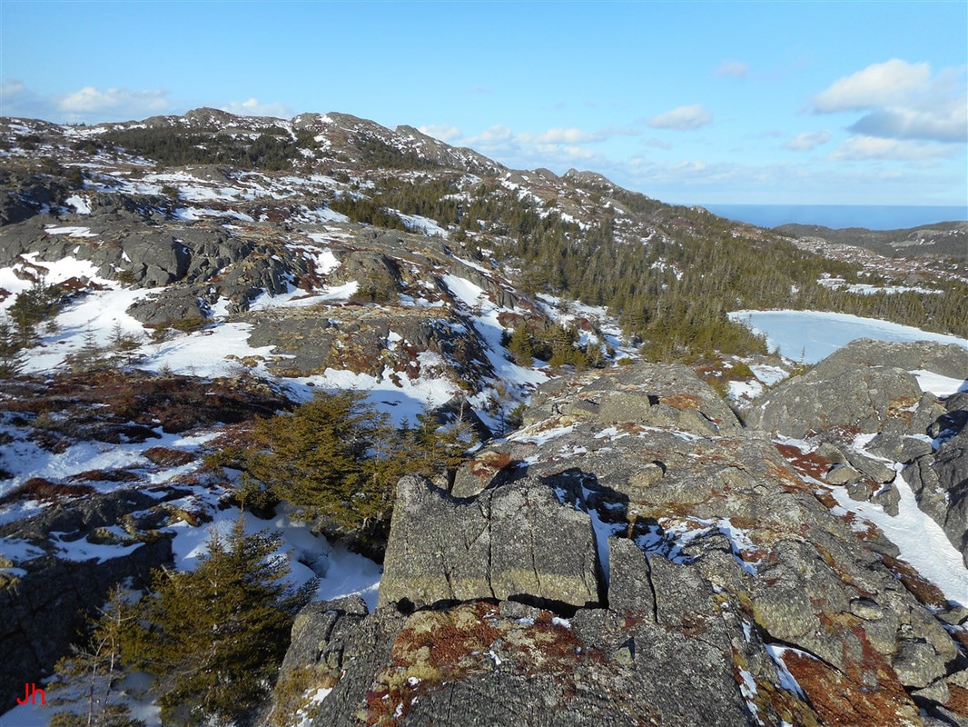
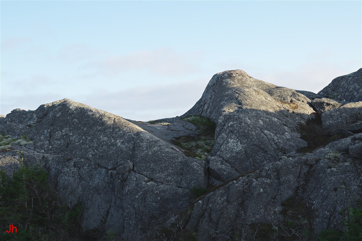
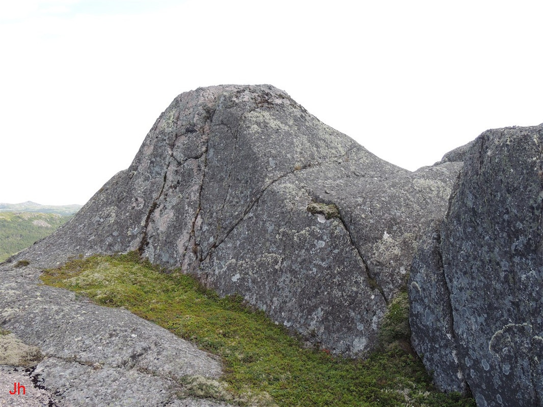
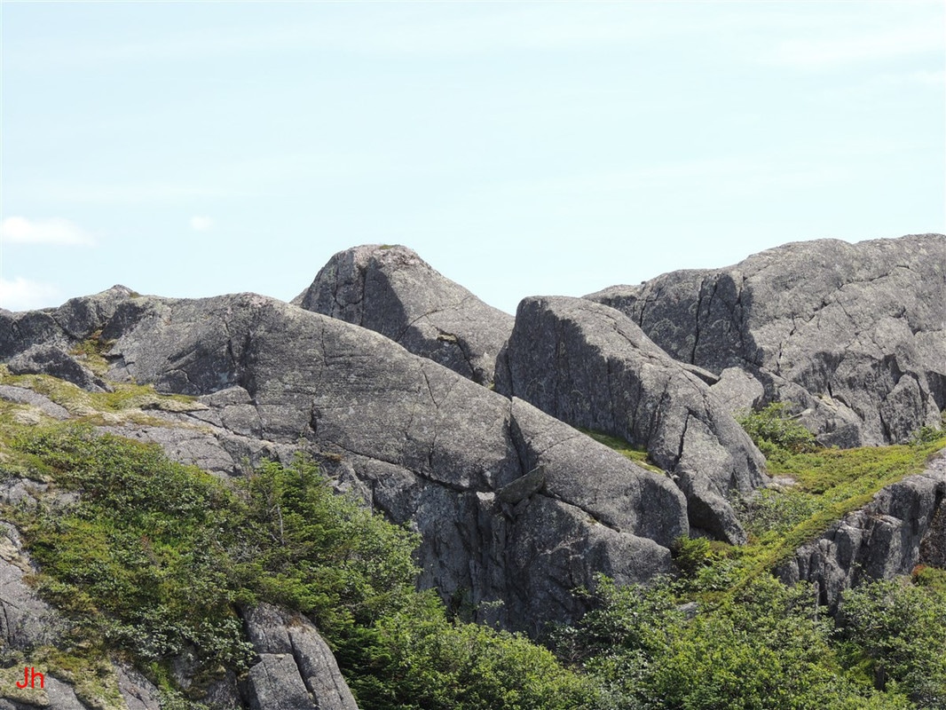
Illustrative Feature 06 comprises the split flat-topped ridge appearing in the foreground of the above photograph. The ridge is divided by a narrow steep-sided valley carved by basal-slip glacial erosion. Diverse occurrences of ice-disrupted bedrock on this ridge suggest that, following a stage of temperate glaciation, cold-based glacial ice became established and then deglaciation occurred without a return to temperate ice conditions.
lllustrative Feature 06 will be used to introduce a model for bedrock disruption on the Isthmus of Avalon where the key process responsible for breaking and shifting bedrock is subglacial ice segregation. Within the context of this model, subglacial pore water is assumed to collect under pressure within bedrock, a legacy of millennia of deep burial under thick temperate ice. The pore water (premelted ice) remains mobile as permeable bedrock then transitions to subfreezing temperatures. During cold deglaciation (deglaciation where the temperature at the ice-bedrock interface remains constantly below the pressure melting point) subglacial ice pressure declines and pore water migrates toward the cold glacier base, segregating into ice masses that initiate and accumulate in joints and fissures in subglacial bedrock. Heat is removed to the surface from the glacial base via conduction and advection.
The presentation of this illustrative feature will be divided into two sections. Firstly, a set of individual disrupted bedrock features will be identified and described. Secondly, a discussion and analysis of these features will be presented and their significance in supporting the subglacial ice segregation/cold deglaciation model will be considered.
Local topography:
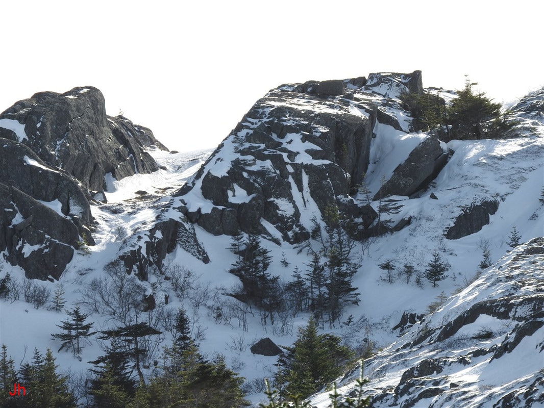
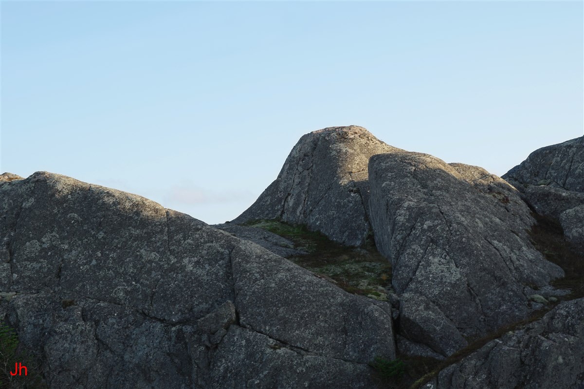
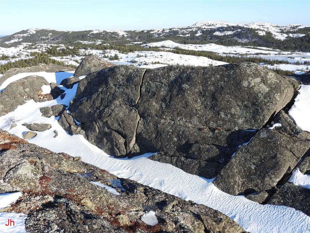
The split ridge, IF-06 appears near the center of the above winter photo, taken with the camera pointing in a southerly direction.
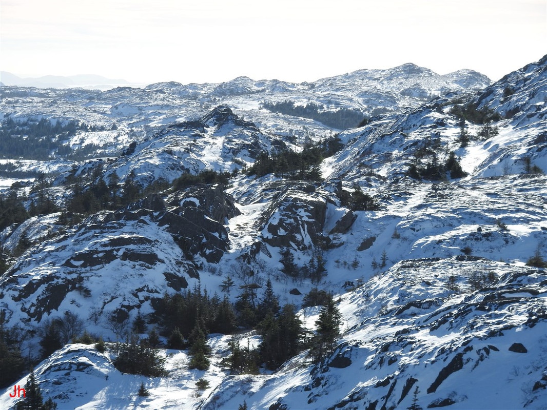
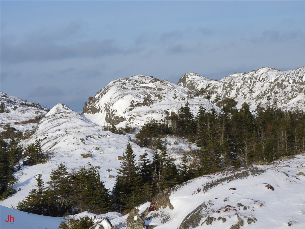
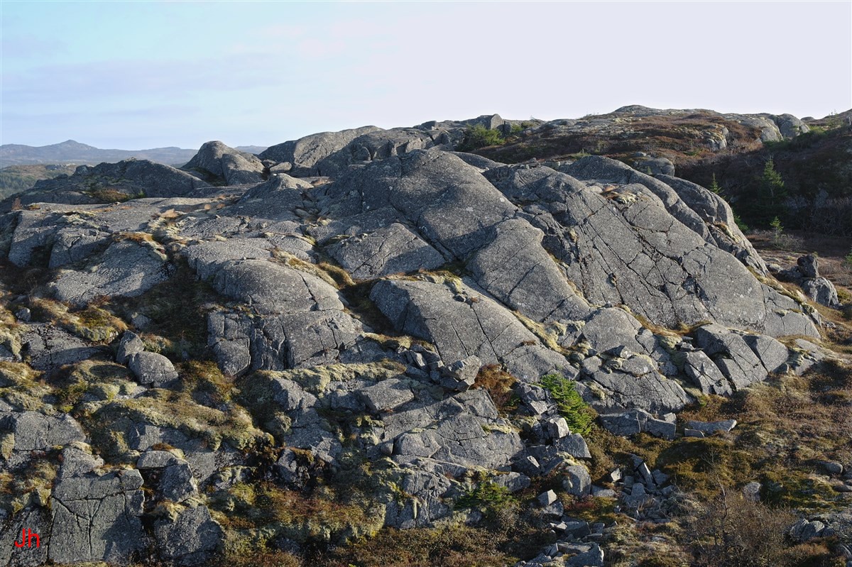
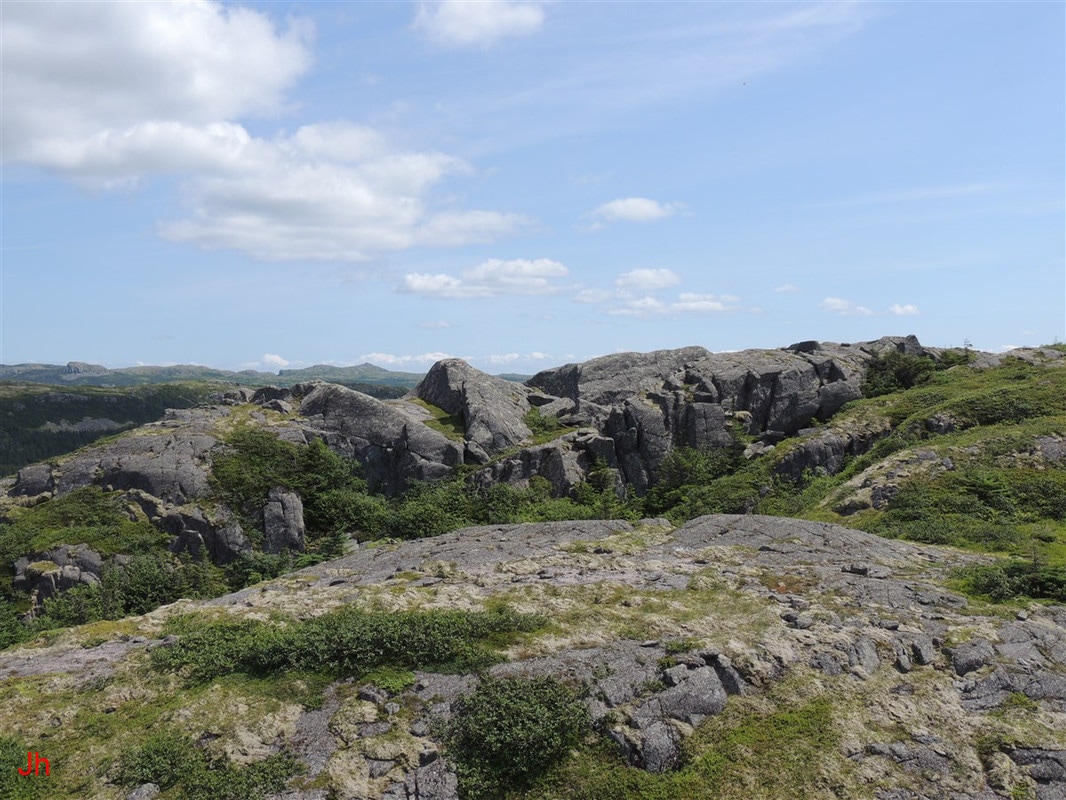
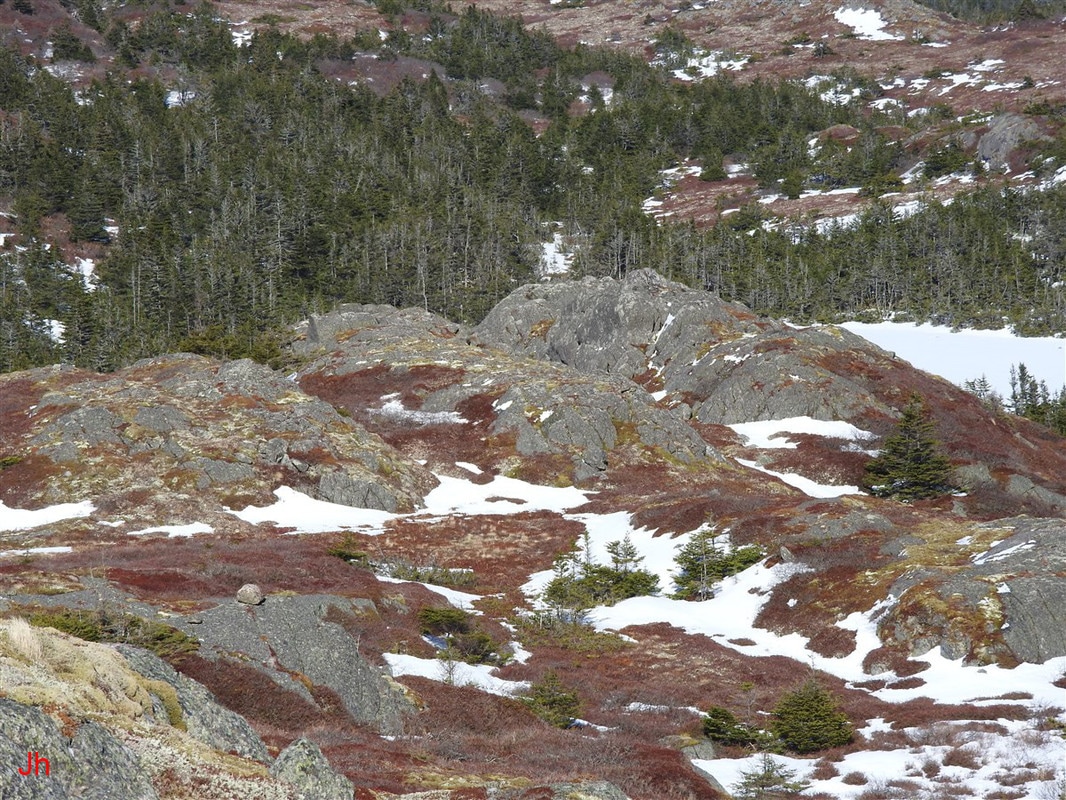
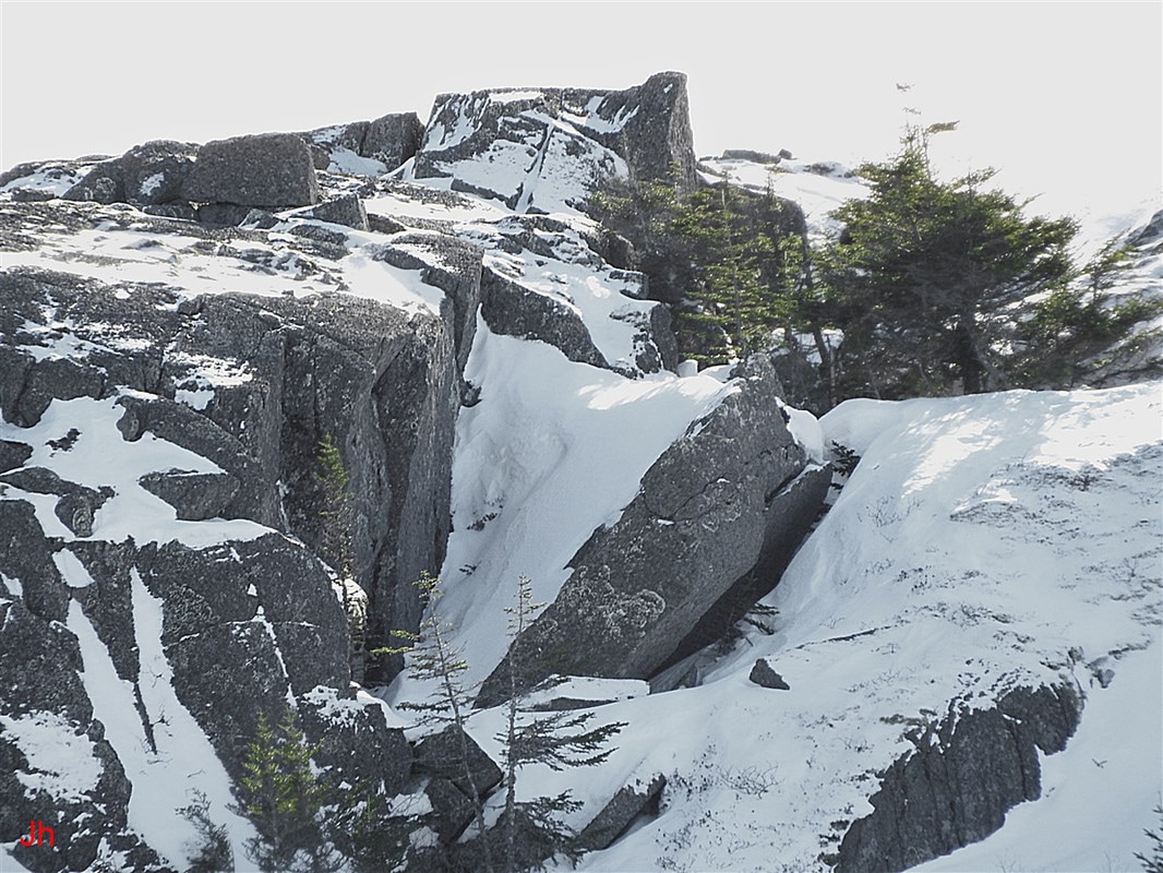
The above photo shows the view looking north from the same viewpoint as was used for the previous picture. The rugged topography shown in the two photos is potentially significant in two ways. Firstly, the topography would tend to impede near-ground motion of a cold-based glacier, trapping the glacier and reducing creep velocities at near-ground heights. Low basal creep speeds would, in turn, allow ice emerging from the bedrock (non-tangential glaciation, Technical Note 6) to match or exceed tangential ice-flow speeds creating a net ice velocity vector not dominated by the tangential component. Secondly, cold glacial ice moving via creep over rugged topography would undergo mixing whereby ground-level ice would blend with potentially colder upper-level ice. Advective heat transfer from the glacial base would thus be enhanced by ice flow over the rugged topography.
Location relative to previous illustrative features:
Location relative to previous illustrative features:
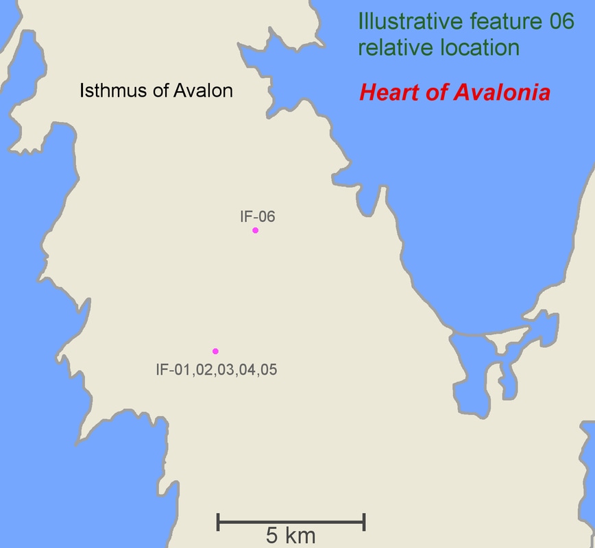
As illustrated on the above map, IF-06 is located about 4 km northeast of the local area where IF-01 to IF-05 are located. The line connecting the two areas runs roughly parallel to the axis of folding of the Isthmus bedrock by Silurian-Devonian tectonic compression. Both areas overlie volcanic rock, tuff and ignimbrite, and the areas lie along an anticline, with erosion having exposed an earlier bed in the volcanic sequence comprising the Bull Arm Formation. The rock shows evidence of metasomatism which appears to have preceded or accompanied regional metamorphism.
The main difference in the glacial environment at the two locations shown above relates to late-Pleistocene ice flow velocity. Disrupted bedrock features at the southwesterly location show consistent evidence of unidirectional ice flow occurring up to the time of completed deglaciation. At the northeasterly location, there is no evidence of a preferred late-stage ice flow direction. Rather, plucking has occurred almost at random on various hills and indications of ice flow direction based on plucking and bedrock shift are inconsistent and contradictory. This observation is useful in supporting the cold deglaciation/subglacial ice segregation model (see discussion and analysis). Both locations show abundant evidence of pronounced basal-slip glacial erosion by earlier-stage warm-based glaciers that flowed mainly in the direction of the nearest coast.
IF-06 area overview:
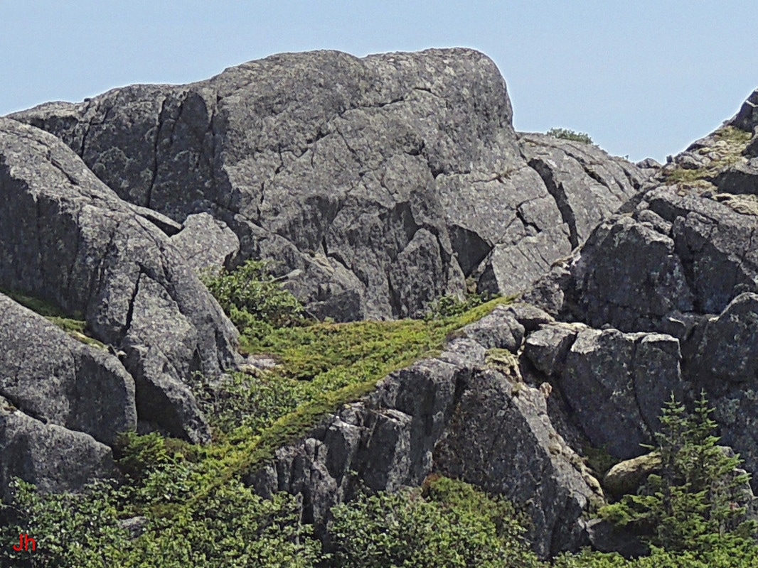
In the above southerly-directed view, the split ridge, IF-06, appears at the center left of the frame. Note the highly disrupted west-facing side (right side on photo) of IF-06.
In the above easterly-directed view, IF06 appears in the background, behind a low foreground hill comprised of bedrock shaped by intense basal-slip glacial erosion. The foreground bedrock surface has undergone little post-basal-slip bedrock disruption in sharp contrast to the equivalent west-facing slope of IF-06.
In the above photo, the plucked west-facing slope of IF-06 is seen from the top of the bedrock hill that was pictured in the foreground of the previous photo.
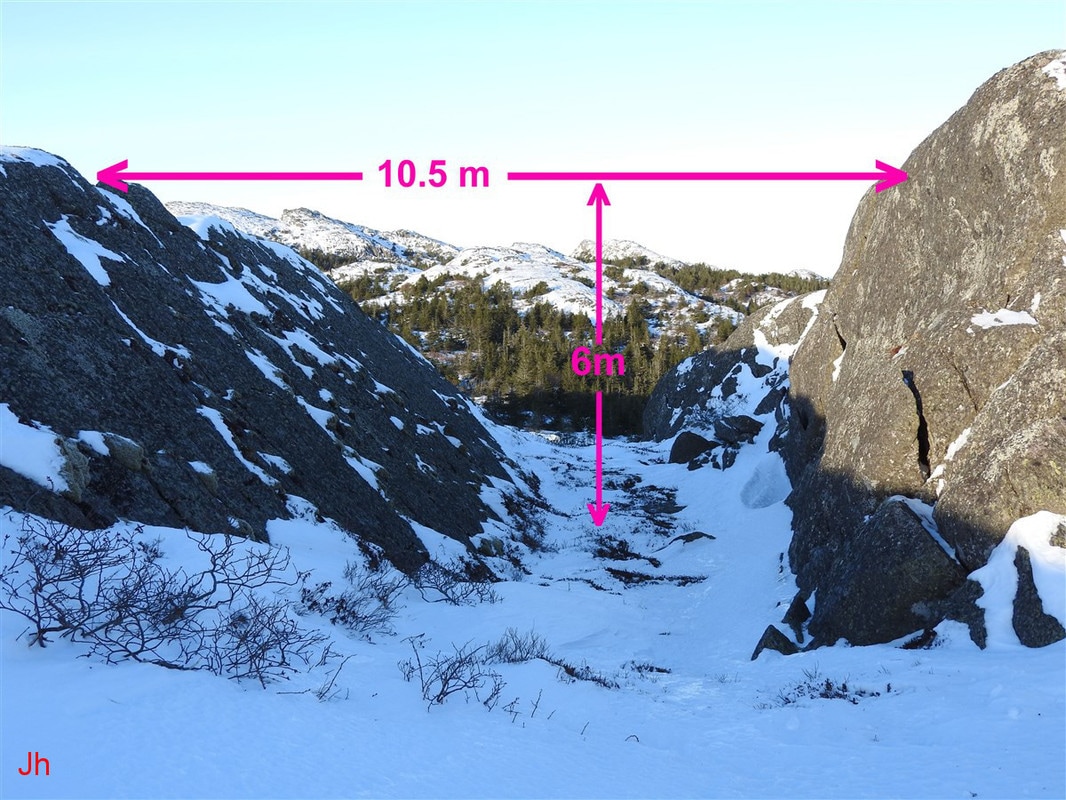
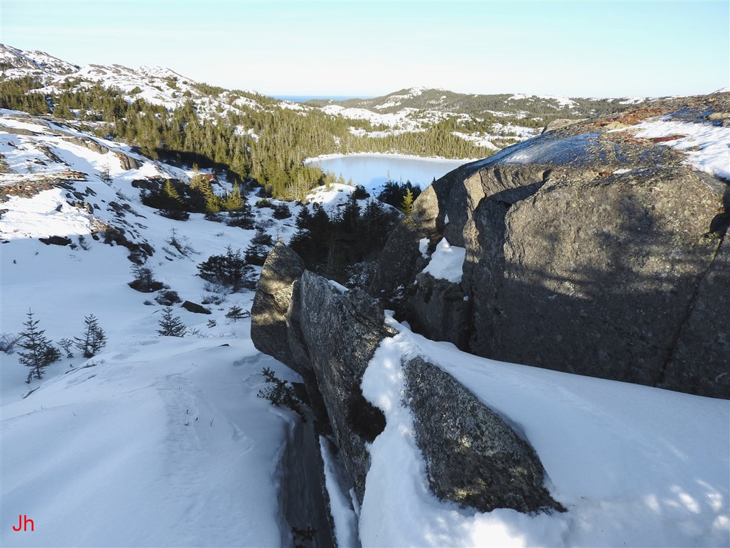
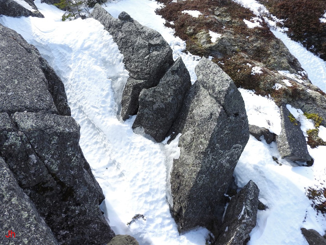
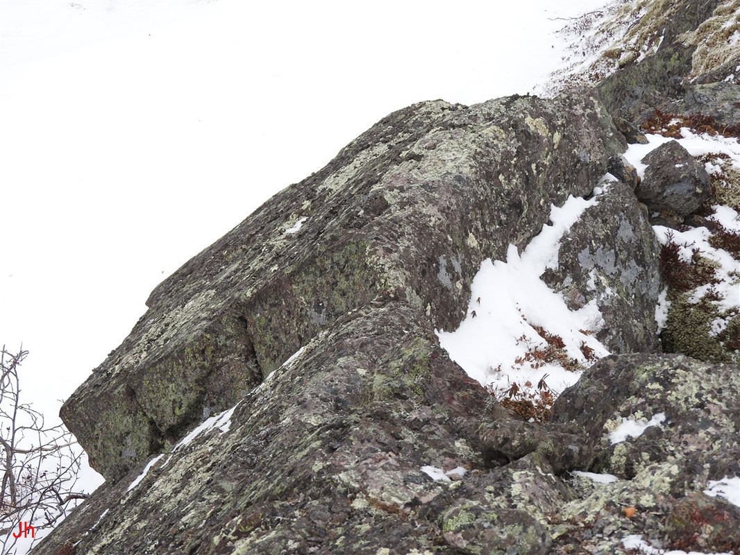
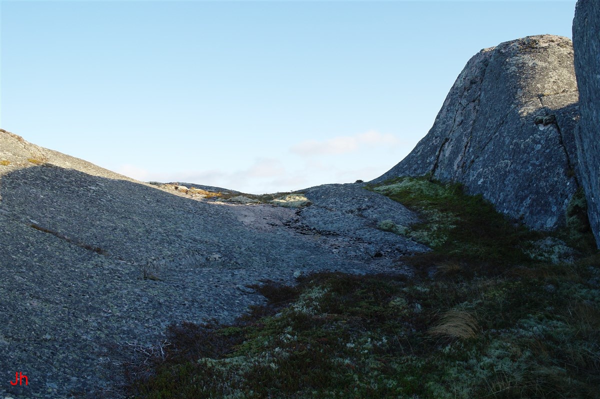
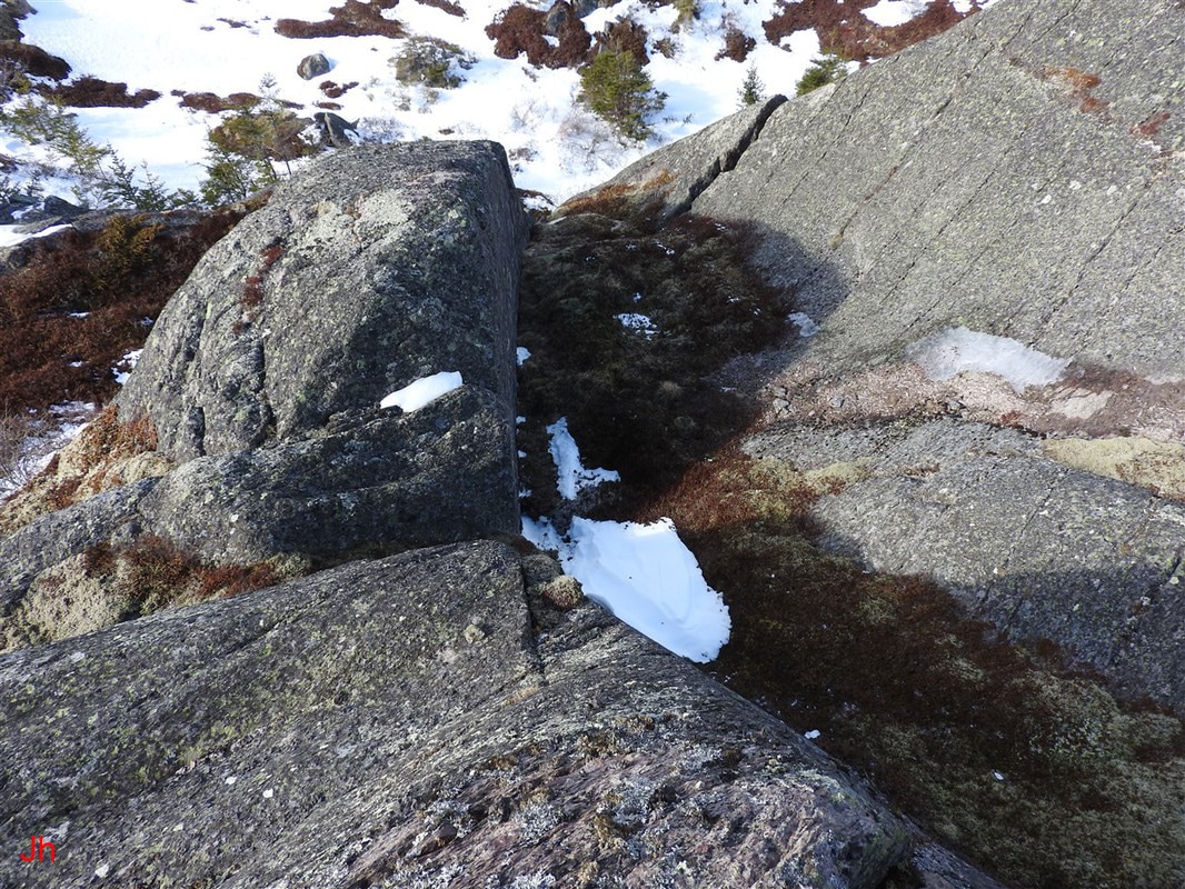
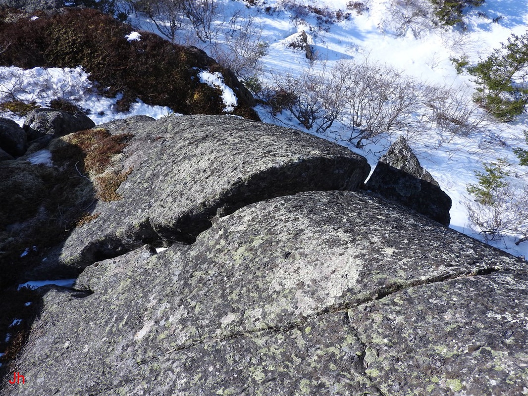
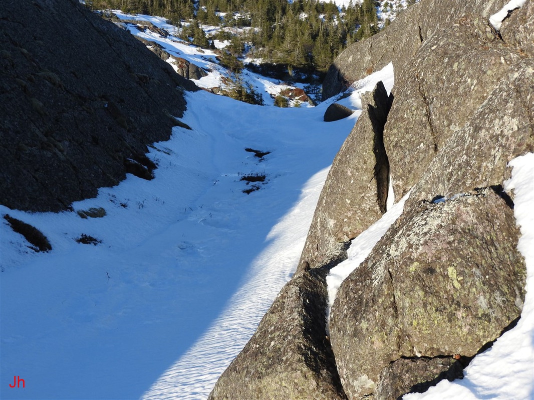
The cross-sectional shape of the of the west section of the ridge, IF-06, is shown in the above photo taken from northeast of the feature, looking southwest. A view of the center valley dividing the ridge is shown below, along with a second photo showing scale.
The photo below shows the ridge, IF-06, viewed from the southwest, looking northeast. The two sections of the ridge are seen at the center of the frame.
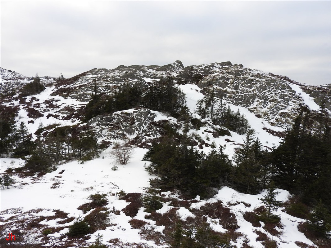
The photo below, taken from east of IF-06, looking west, shows the generally downward-sloping land east of the feature. The crest of the eastern side of the ridge, IF-06, is seen at the top center of the frame.
Site layout and list of individual bedrock erosion features:
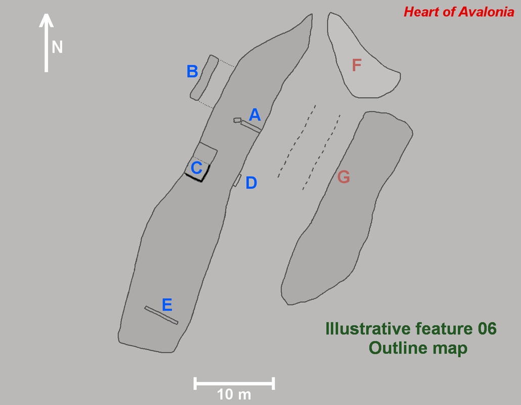
The above layout map for IF-06 shows the locations and approximate sizes of some of the key ice-induced bedrock erosion features. These individual features are briefly described below:
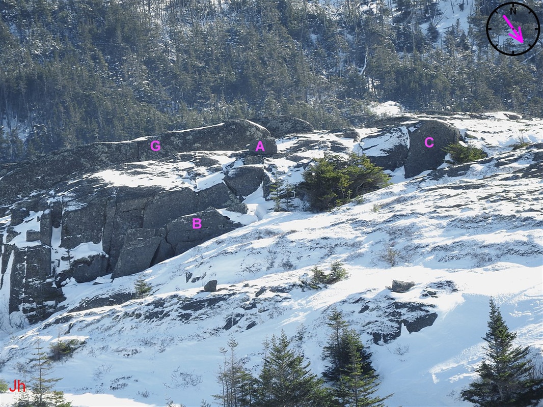
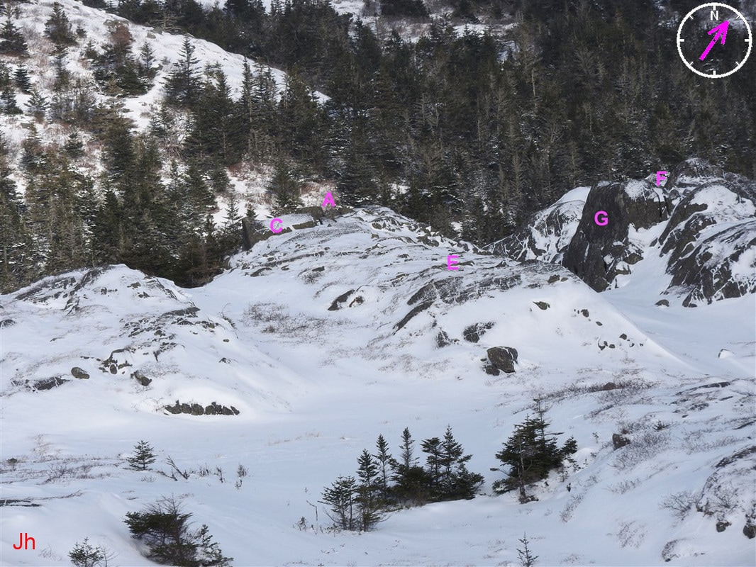
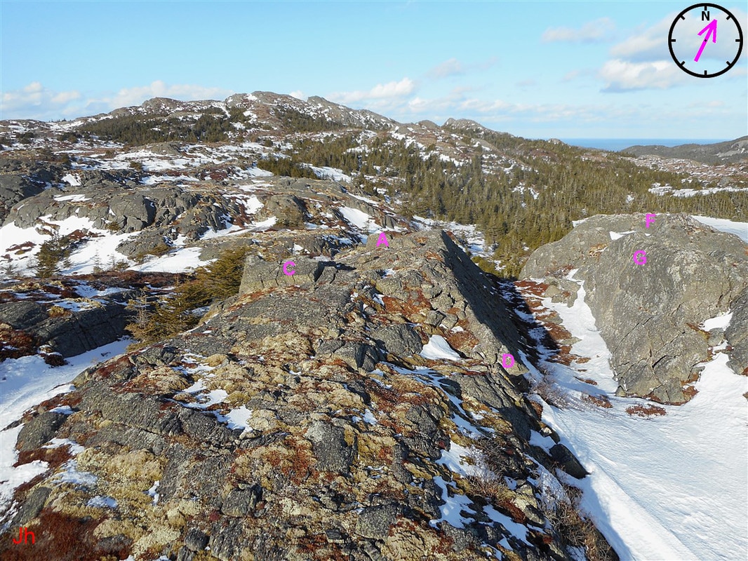
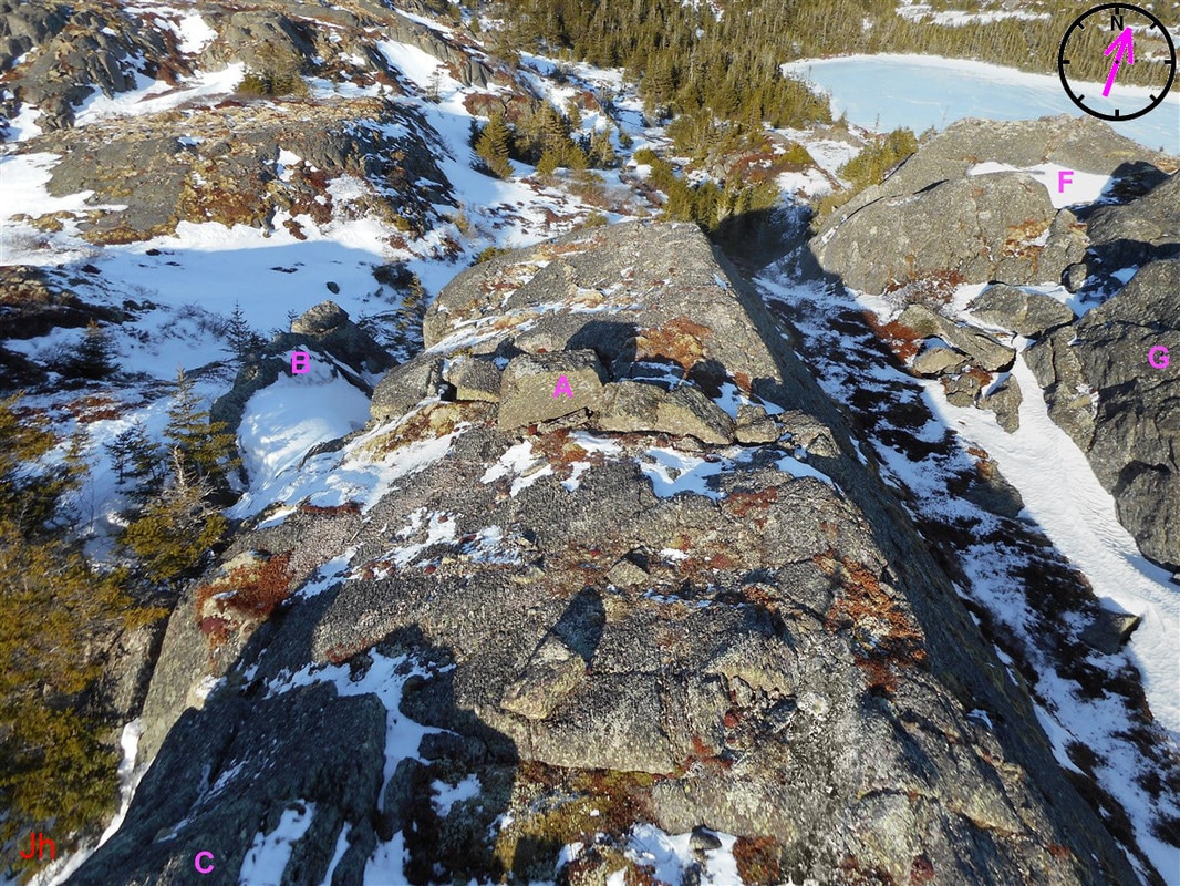
A) A chain of four large to mid-sized vertically frost-heaved joint blocks lying along a narrow fissure.
B) A row of very large slabs of bedrock displaced by rotation from the west side of the ridge.
C) A very large joint block lifted upward by frost wedging and separated from the west side of the ridge by deep fissures.
D) A large frost-heaved joint block displaced upward and outward from the sloping rock face forming the east side of the center valley.
E) A chain of low vertically frost-heaved joint blocks.
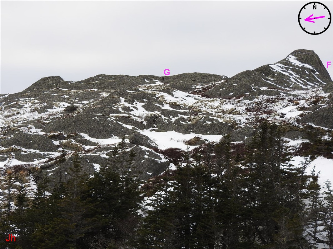
F) A prominent bowl-shaped basal-slip glacial erosion feature.
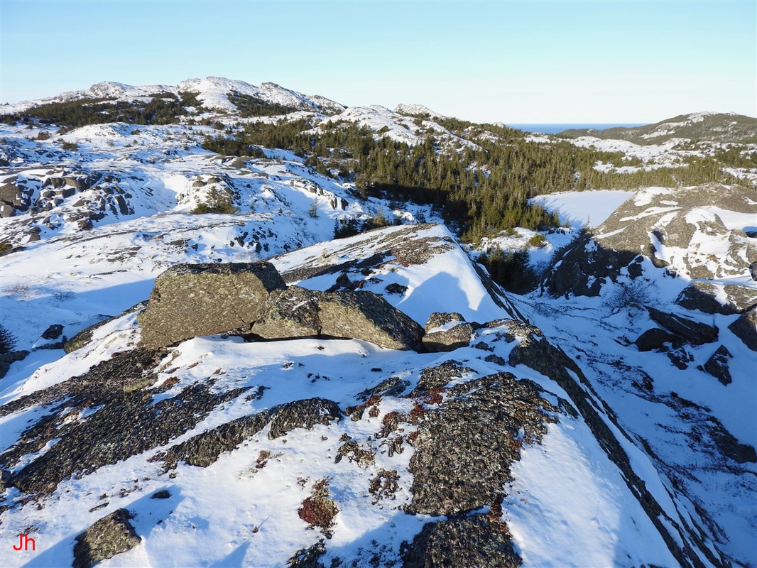
G) A rock face incorporating multiple large, narrow fissures following longitudinal jointing (delaminated rock face).
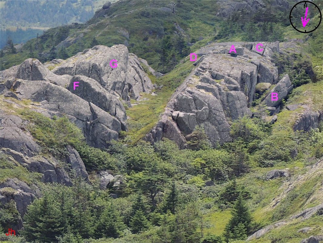
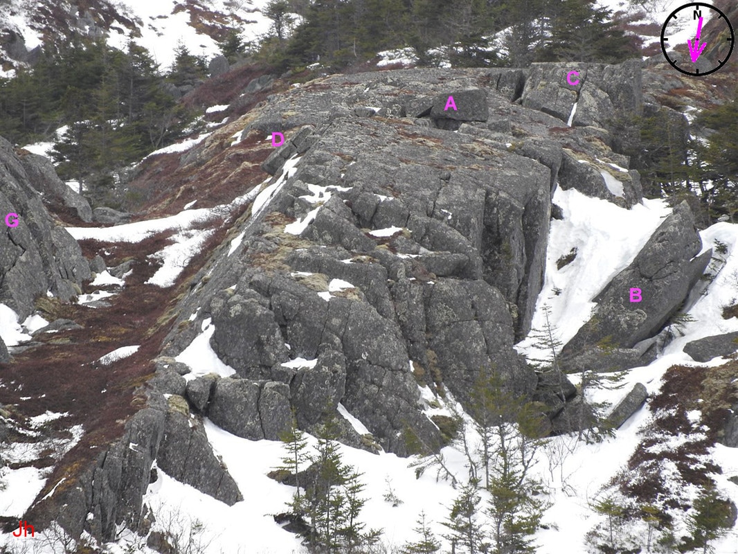
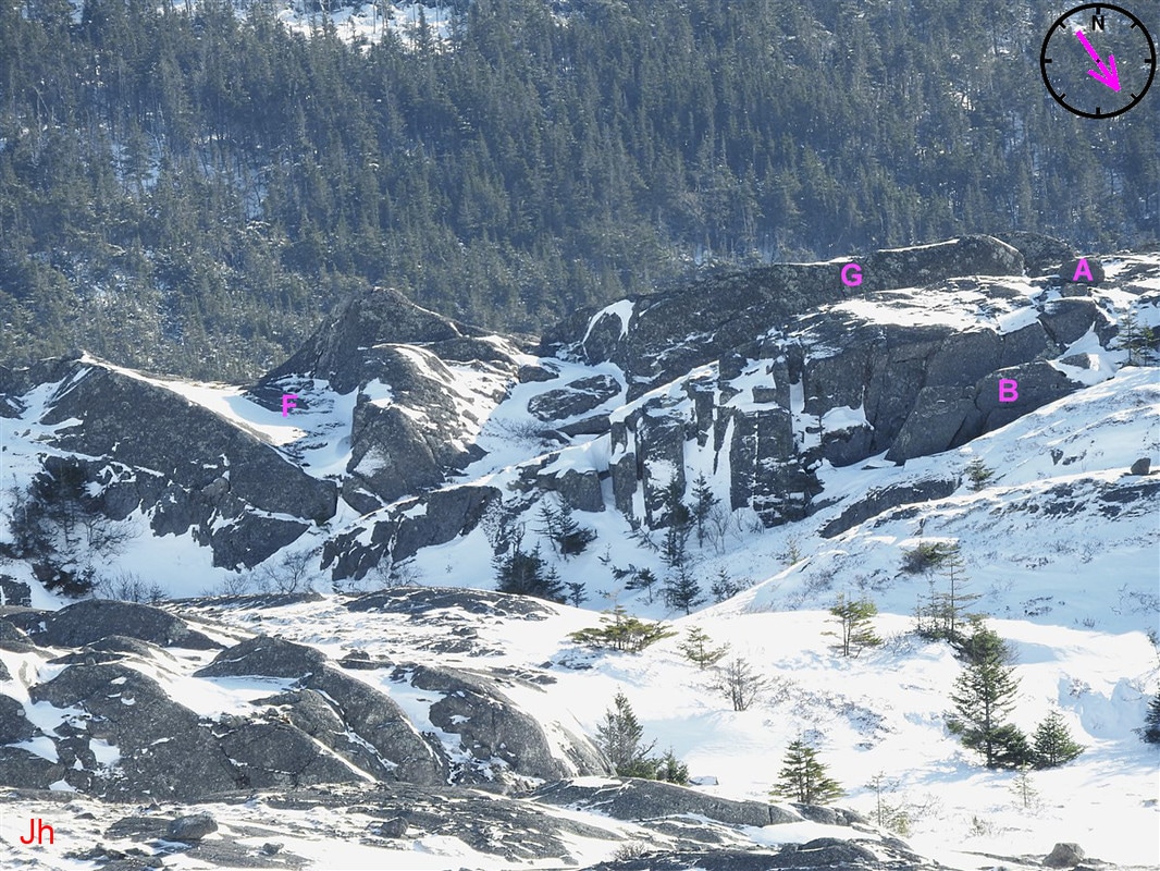
The following set of photos show the various features viewed from different directions. The compass appearing in the upper right corner of each photo indicates the direction in which the camera was pointed when the photo was taken. The letters identifying the features correspond to the above layout diagram and to the above list of individual features.
Descriptions of the individual features:
A) Frost-heaved joint blocks
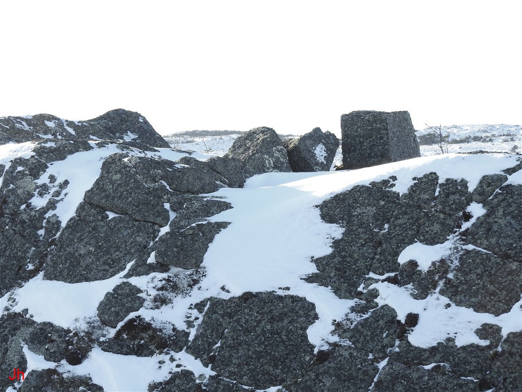
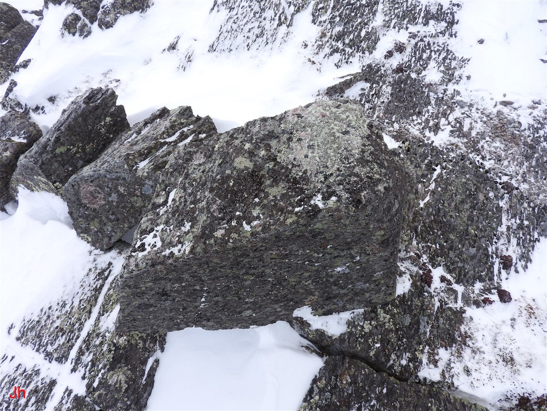
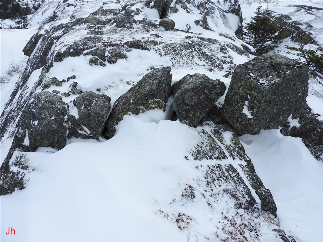
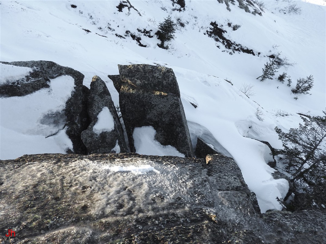
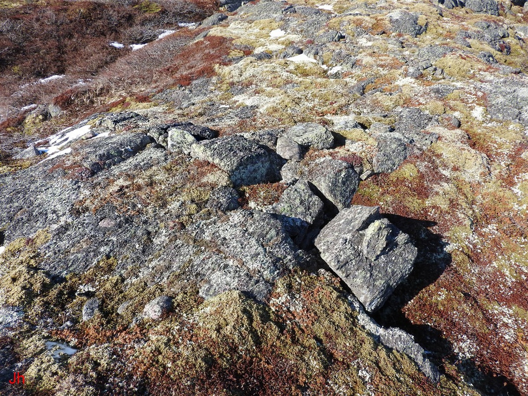
Four frost-heaved joint blocks on top of the west section of the ridge, IF-06, are shown in the above photo. The row of blocks is 3.2 m long and the individual blocks are each about 0.6 m wide. The left-most block is completely dislodged from bedrock and is displaced from its point of origin. The block immediately to the right of the dislodged block is partially dislodged, while the two rightmost blocks remain rooted in bedrock. The following set of 8 pictures shows the bedrock frost heave occurrence as viewed from several different angles.
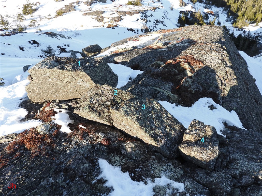
The four individual joint blocks were shifted upward by frost heave, then tilted top-westward and shifted westward. The amount of tilt and horizontal displacement on each block increases east to west. The photo below assigns numbers to the blocks to aid in the discussion that follows.
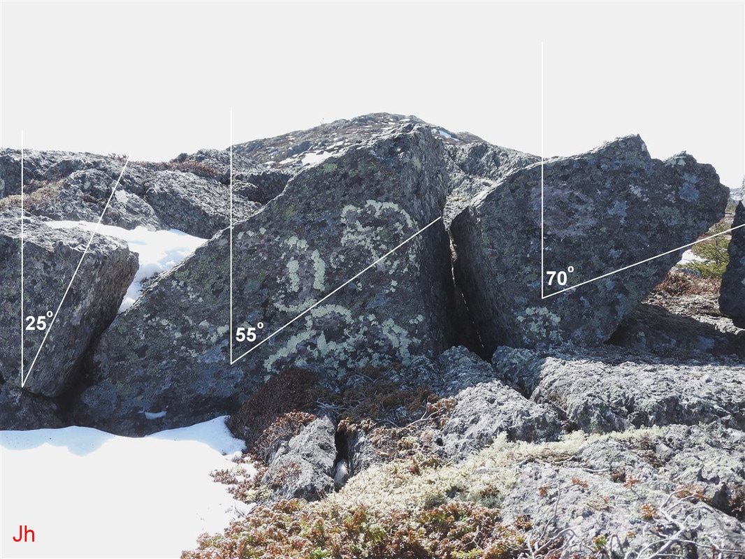
Changes in the orientations of the blocks during frost heave were inferred by looking at the foliation in the blocks. Several fissures following longitudinal joints in the west section of the ridge, IF-06, were examined to determine the dip of the foliation in the surrounding bedrock. This dip was approximately 90 degrees. The ice-induced tilt of the frost-heaved joint blocks was therefore reflected in the deviation of the slope of the foliation in the individual blocks from vertical. The net rotation of block 1 can be described in terms of two sequential rotations. First, the block was rotated 90 degrees about a horizontal axis from its initial orientation in bedrock. The former top of this block (top surface before the block was dislodged) now points roughly westward. Second, the block underwent a counterclockwise (looking down) rotation about a vertical axis by about 30 degrees. The original southwest-facing side of block 1 (face shown in the above photo) now faces approximately south. The tilts of blocks 4, 3 and 2 are shown in the following diagram.
In the above photo, block 4 is on the left. Block 2 is partially dislodged from bedrock, with the north (foreground) side of this block lifted out of the underlying gap and resting on the bedrock surface. Block 2, like block 1, has rotated slightly counterclockwise (looking down) about a vertical axis.
In addition to rotations, blocks 1, 2 and 3 underwent translations toward the west. The gap from which the blocks emerged terminates at the west side of block 2. Block 1 was thus apparently shifted westward by about 30 cm after it was dislodged and block 2 was shifted westward by an amount roughly equal to the thickness of block 1 (70 cm).
In addition to rotations, blocks 1, 2 and 3 underwent translations toward the west. The gap from which the blocks emerged terminates at the west side of block 2. Block 1 was thus apparently shifted westward by about 30 cm after it was dislodged and block 2 was shifted westward by an amount roughly equal to the thickness of block 1 (70 cm).
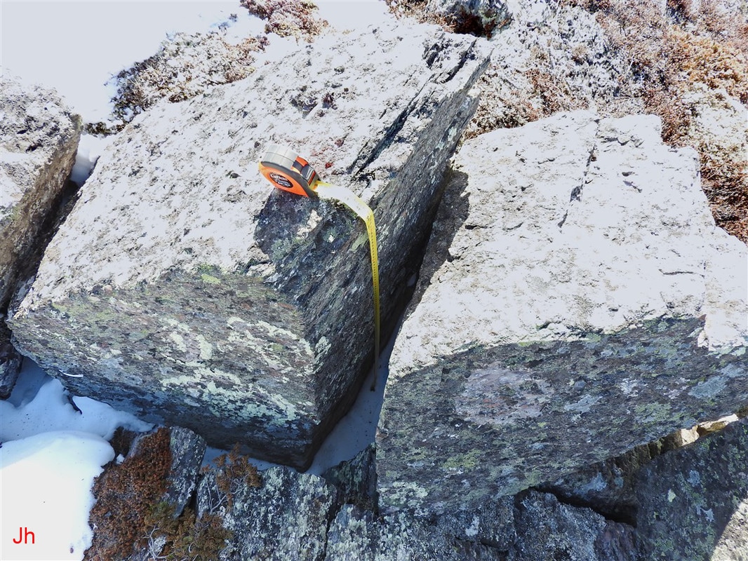
The above photo shows block 3 (left) and block 2. The tape reads 120 cm where it first bends, extending down through the snow to a point where the end of the tape contacted bedrock, debris, or ice. Block 3 underwent a combination of rotation and translation. It appears that the sloping upper surface of block 3 originally mated with the side of block 4 just visible at the left edge of the photograph.
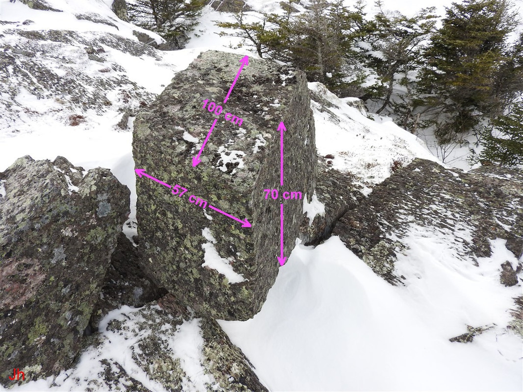
The dimensions of block 1 are shown in the above photo. This block has a volume of about 0.4 cu. m, representing the minimum volume of intruding ice needed to dislodge the block from bedrock. Each of the blocks 1 through 4 had widths matching block 1 (range 57-60 cm).
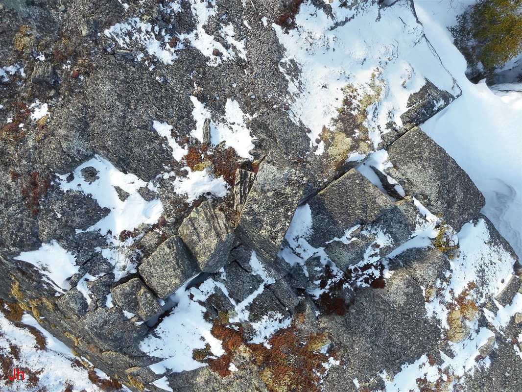
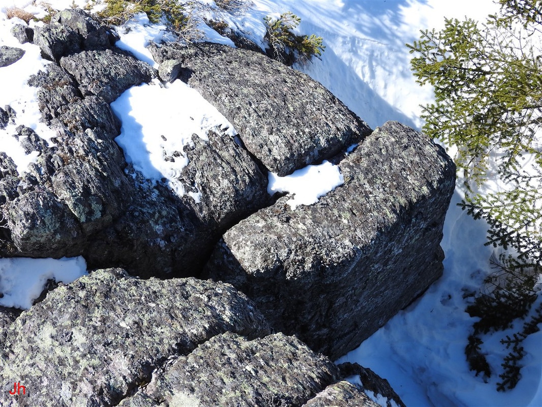
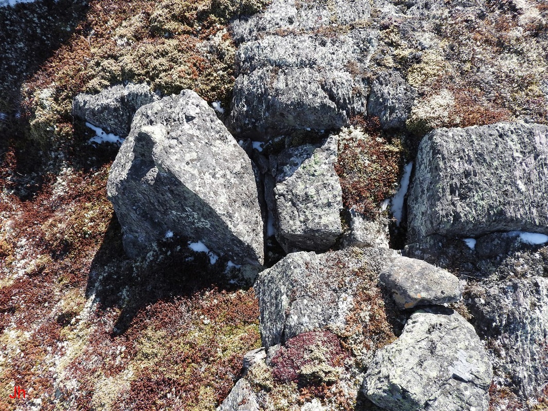
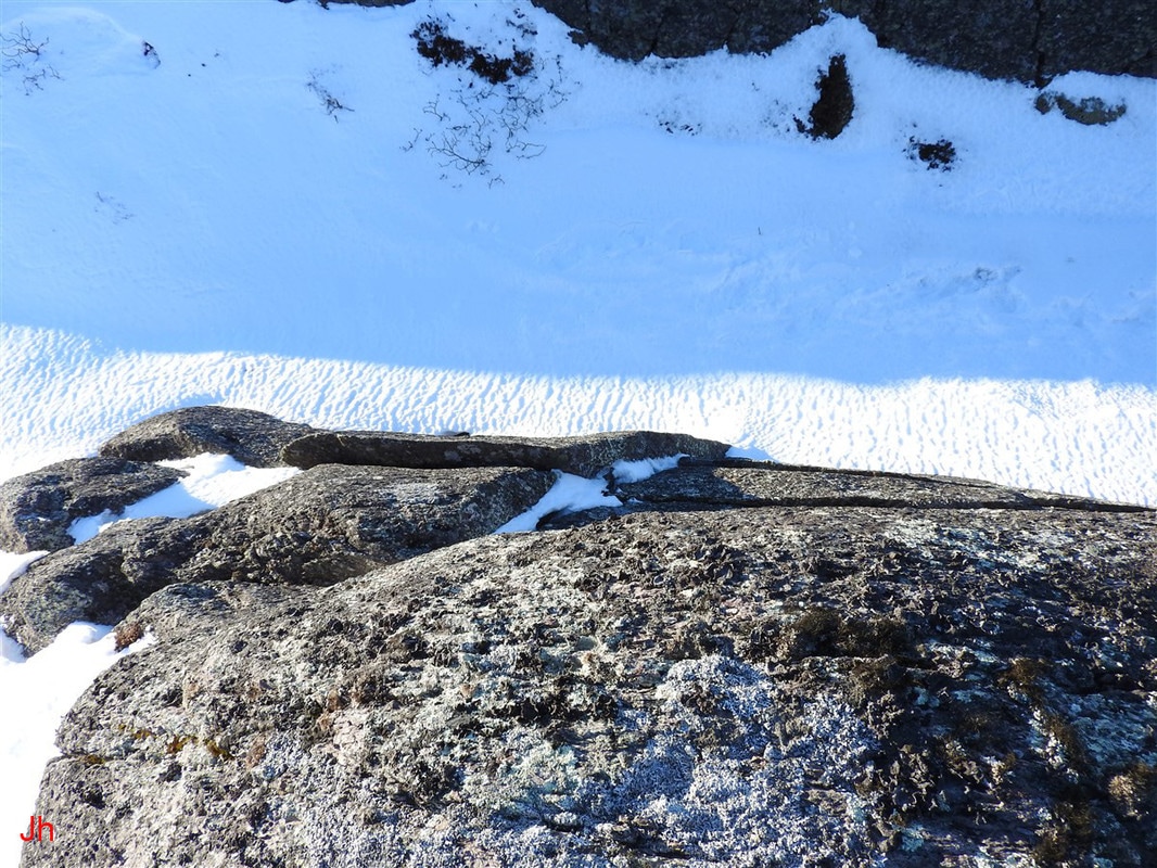
An overhead view of the row of blocks (A) is shown in the above photo. A close look at this photo reveals a narrow fissure forming the north (lower right on photo) edge of the gap from which the blocks emerged. The fissure appears to terminate at block 4, but extends west to the edge of the ridge. Note the abrupt drop off into snow at the west edge of the ridge (upper right in photo). This edge marks the boundary from which the southern-most of the very large rotated slabs (feature B on layout map) separated. Joint blocks lying just west of block 1, but on the north side of the fissure, experienced significant vertical frost heave and westward horizontal displacement, as seen in the following photos.
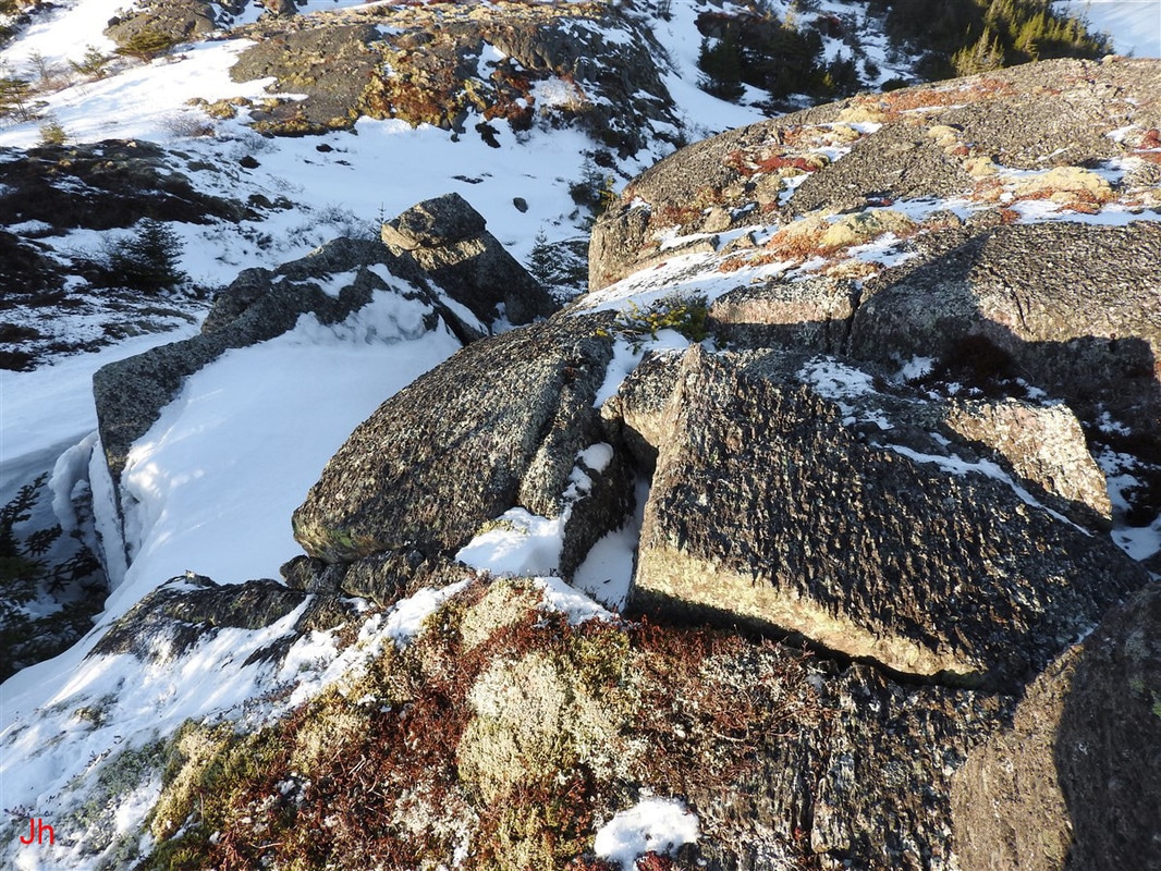
The first (left) photo above looks northwest and shows frost-heaved joint blocks in the foreground. The fissure described above corresponds with the foreground edge of the frost-heaved blocks. The large rotated slabs (B) are seen in the background. The second (right) photo above shows the same frost-heaved blocks, viewed with the camera directed northeast. Block 1 is also visible in this second photo.
The above west-looking photo shows the sloping rock face east of the row of frost-heaved joint blocks. This rock face forms the west side of the center valley that divides the ridge, IF-06. The significant fissure that forms one side of the row (A) of frost-heaved blocks (see above) does not extend to intersect this rock face.
Interpretations of the observations of the row (A) of frost-heaved joint blocks are provided in the discussion and analysis section of this illustrative feature 06.
B) Large rotated slabs
Interpretations of the observations of the row (A) of frost-heaved joint blocks are provided in the discussion and analysis section of this illustrative feature 06.
B) Large rotated slabs
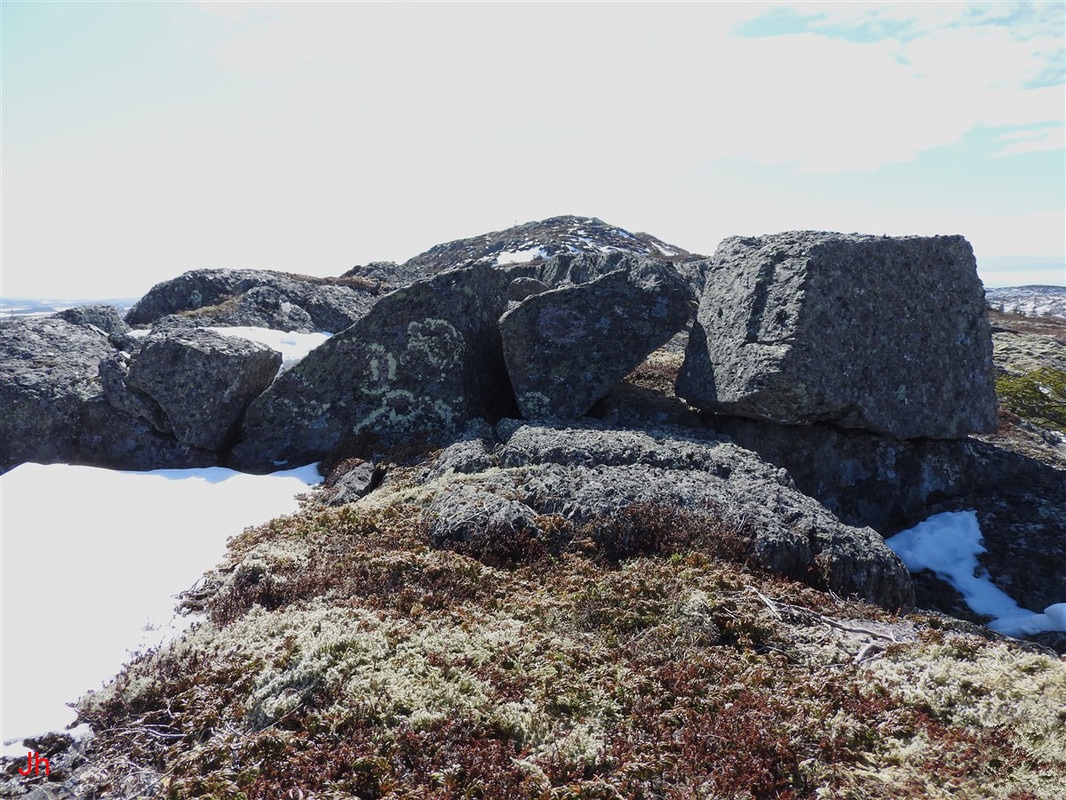
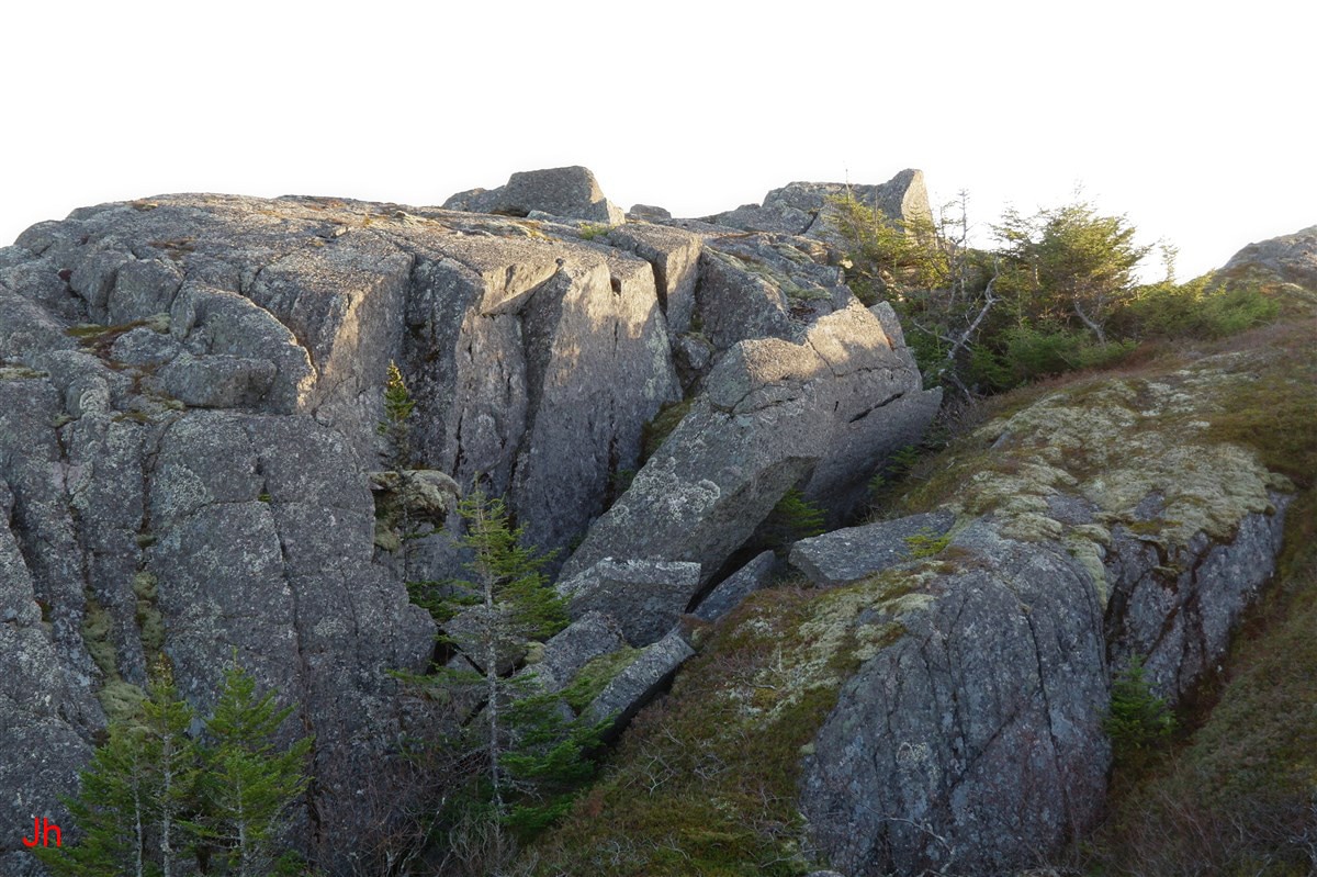
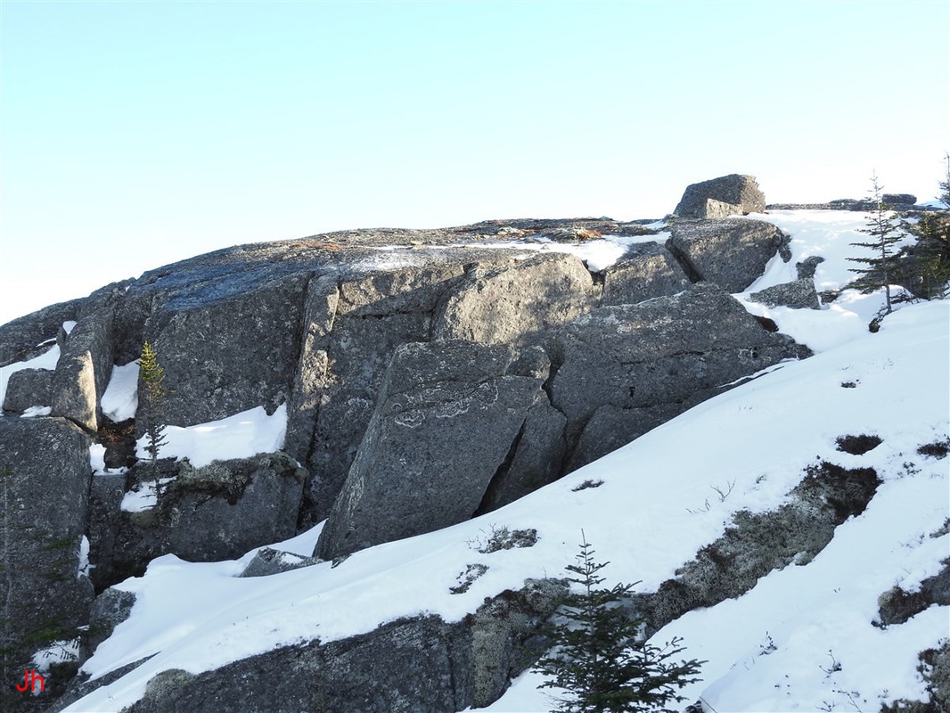
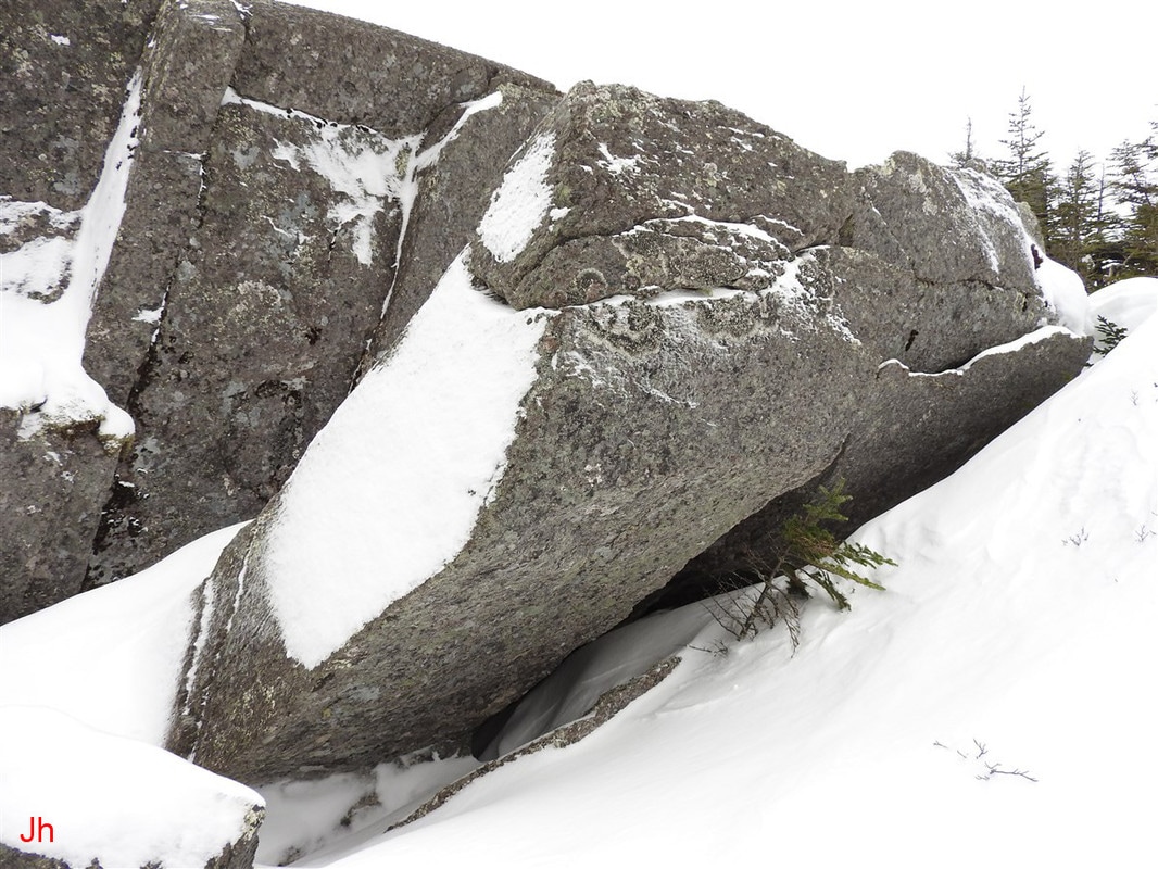
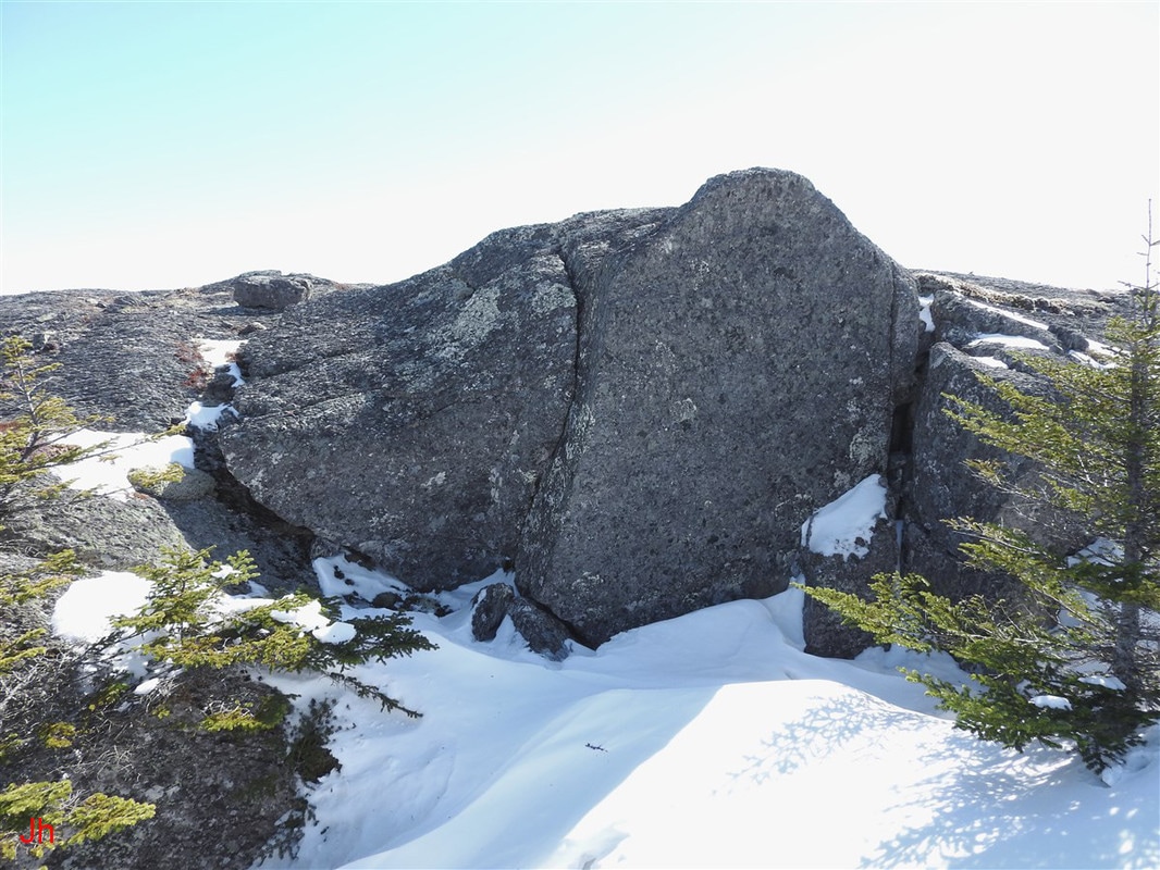
The above photo shows the west side of the ridge, IF-06, where large slabs of rock have been rotated outward from the edge of the ridge by ice pressure. This feature provides an example of restricted plucking as defined and described in Illustrative Feature 05. The plucked section of rock is broken into individual large blocks that have each rotated away from the ridge edge by approximately the same angle. Views of the feature from different directions are shown below.
The length of the individual rotated slabs, measured from bottom to top, exceeds 5 m. The slabs reside at a steep angle to the vertical, with little support on the west side to keep them from tipping further toward the horizontal. This fragile cantilevered configuration suggests that the slabs were rotated entirely within glacial ice and that the ice eventually retreated from the area without overloading the slabs' weak resistance to further rotation.
The above picture shows the slab at the northern edge of the rotated-slab feature (B) in a photo taken with the camera pointing southeast. Note the lack of visible support at the base, which lies more than 5 meters below the top of the slab. This precarious arrangement helps rule out two possible origins for the feature. Firstly, the unstable arrangement suggests that the slab did not fall into its present orientation following release from the cliff face by freeze thaw weathering in a subaerial environment. Secondly, the slab did not experience follow-on ice loading by a temperate glacier sliding westward over the ridge, suggesting that it did not separate from the ridge as a result of warm-based glacial plucking.
The four photos above show broken and frost-wedged rock at the base of the large rotated slabs (B). Note the delamination of the slabs evident in the first two photos. Similar delamination along longitudinal cleavage planes is pronounced in rock on the eastern section of the divided ridge, IF-06. The delamination seen above likely preceded the separation of the slabs from the edge of the ridge.
C) Very large frost-wedged joint block
C) Very large frost-wedged joint block
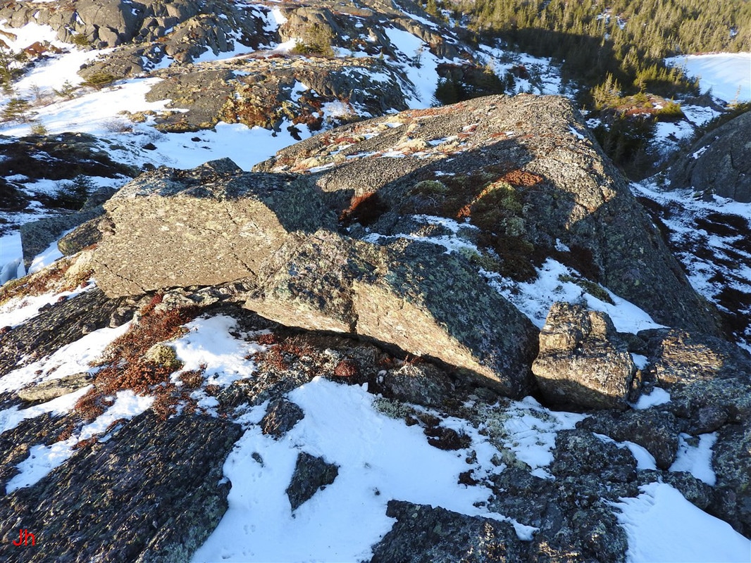
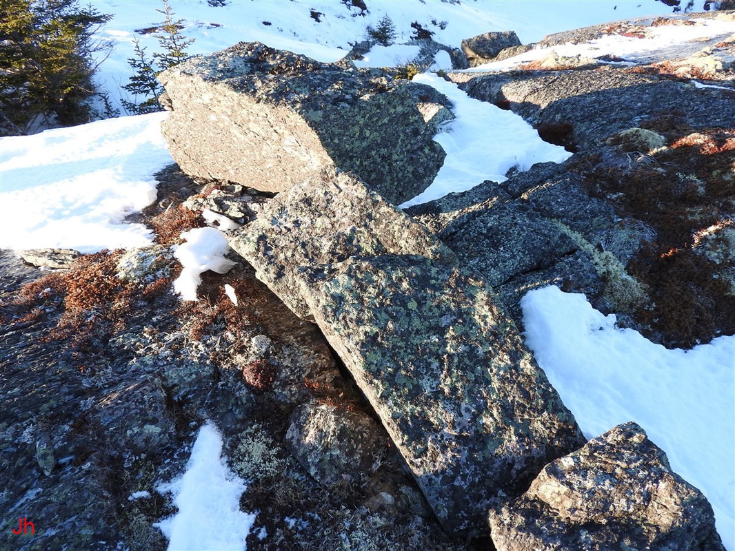
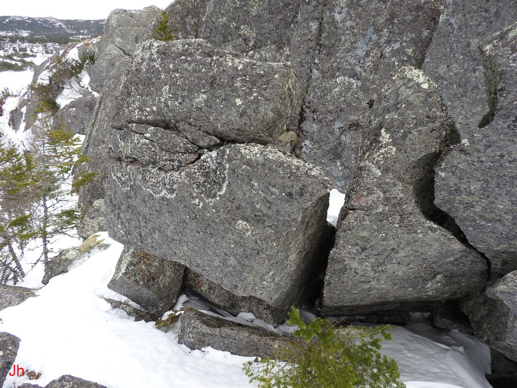
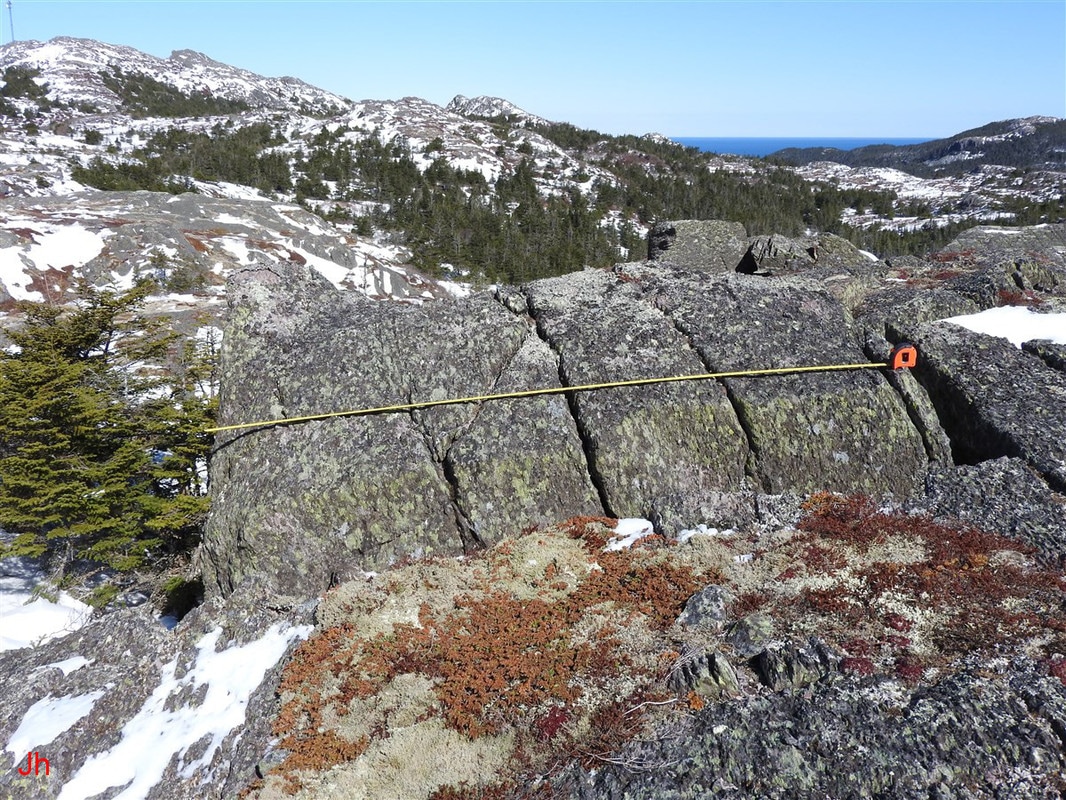
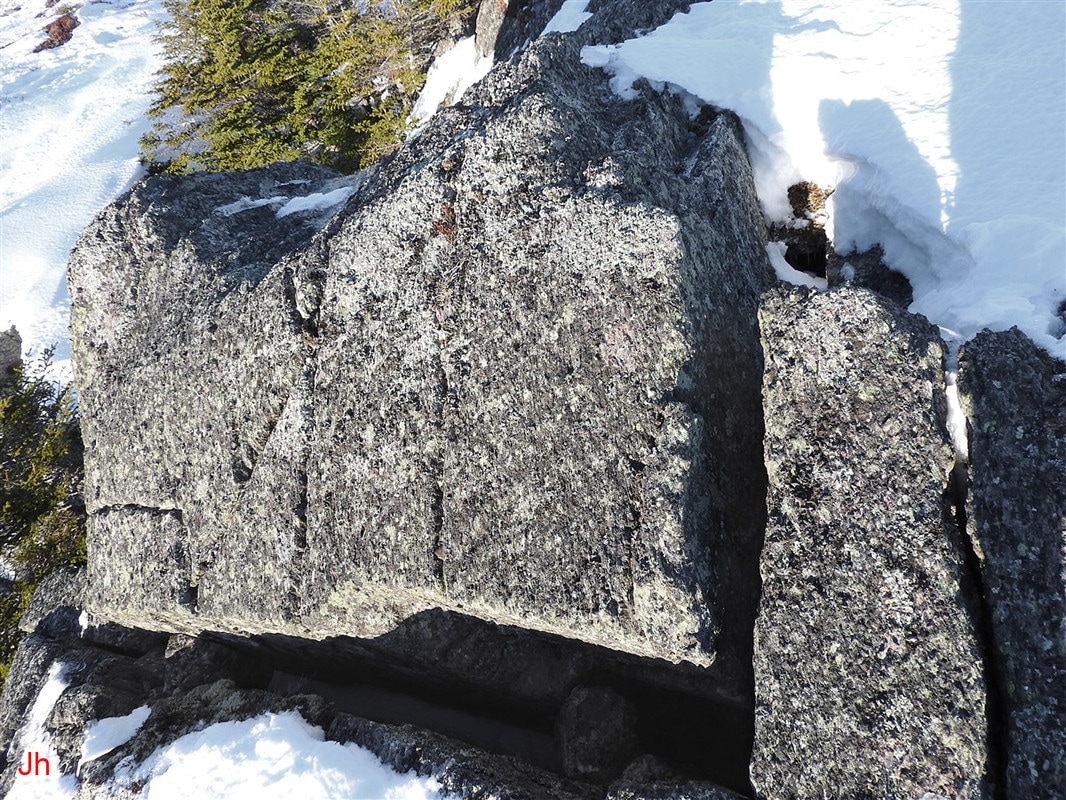
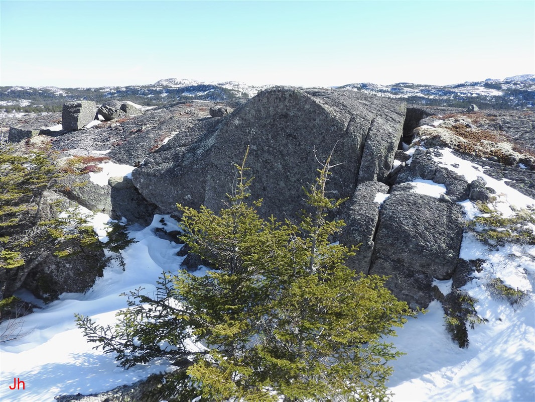
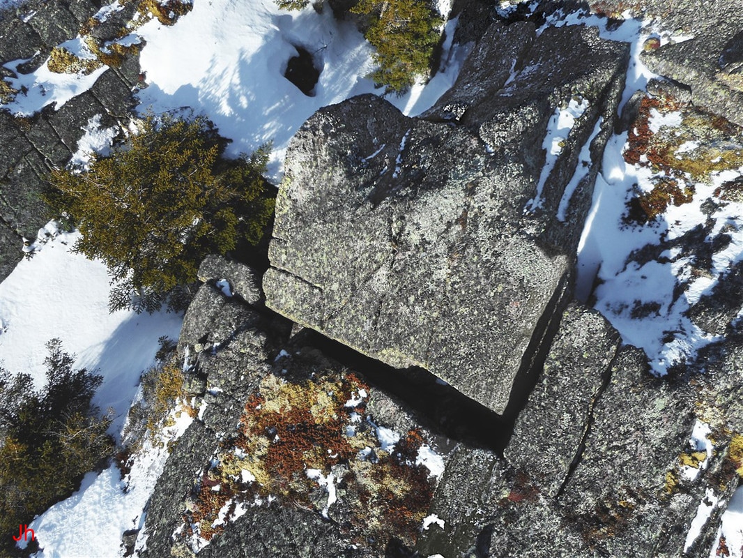
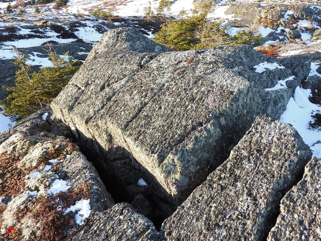
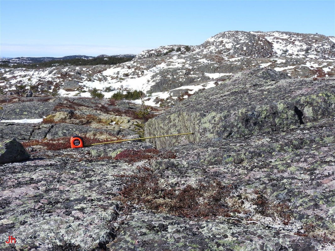
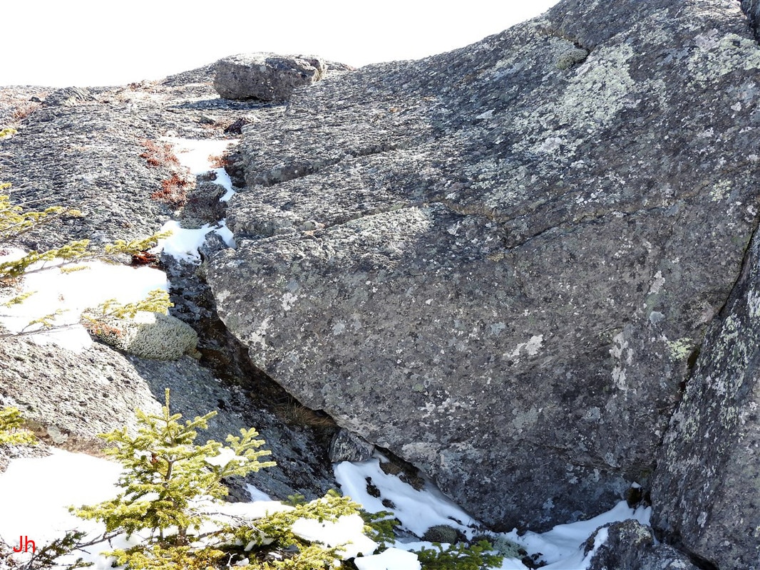
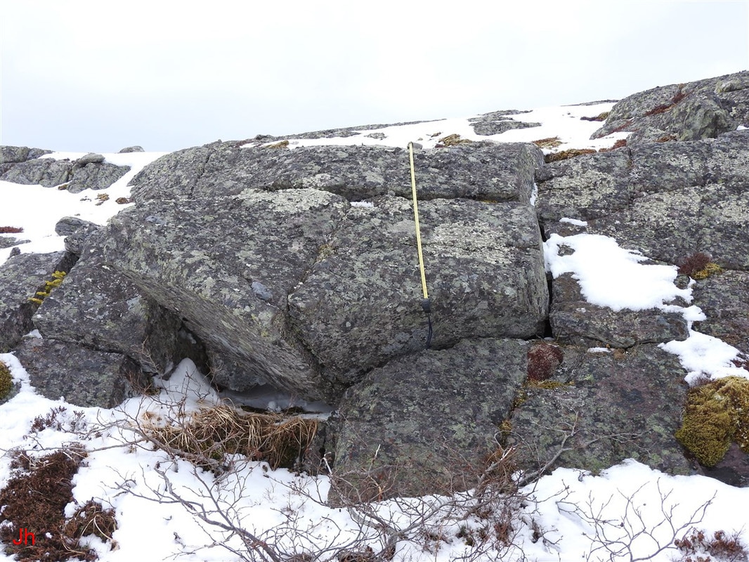
The photo above shows a north-directed view of a very large joint block (C) that has been lifted up and shifted horizontally by frost wedging. The measuring tape seen in the photo extends 2.5 meters (west-east). The feature measures 4.6 m long south-to-north but a fracture at about the midpoint separates the northern portion of the block from the southern portion. The vertical thickness of the block is at least 2.8 meters. Views of the block from several angles are shown below.
As is evident from the above photos, the block was displaced horizontally in a northwesterly direction by ice pressure. The vertical-walled fissures running south and east of the block measure about 2.8 m deep before hitting debris. The south fissure is about 30 cm wide on average, while the east fissure is about 20 cm wide. The block has also been lifted vertically.
The tape seen in the above photo runs roughly parallel to the glacially flattened surface of the bedrock ridge and shows the extent of vertical shift of the block (C). The block has been raised by about 15 cm. This uplift might have been caused by direct vertically-acting frost wedging beneath the block, or it might have been caused by the block sliding upward along a sloping joint that acted as a ramp.
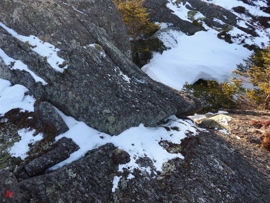
Both of the above photos show the north end of the ice-shifted block (C). It is evident that the north end of the block was forced to ride up over sloping bedrock in response to the opening of the south fissure. The parallel vertical walls of the south fissure indicate that the block did not tip during displacement. Hence the sloping failure plane (fault) beneath the block either extends all the way back to the south fissure or else, the south end of the block was lifted vertically by ice and now overlies a void.
The above photo shows the southwest corner of the ice-shifted block (C) (bottom left of frame) where it pushed up against a separate large joint block (right of center of frame), shifting this block westward as block (C) moved in response to the opening of the east fissure.
D) Frost-heaved joint block on east-facing slope
D) Frost-heaved joint block on east-facing slope
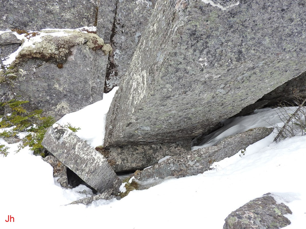
The large frost-heaved joint block shown above measures 1.8 m across, 1.3 m high and is shifted 30 cm outward from the sloping rock face. The block is 0.9 m deep (front face to embedded rear surface). This block is located on the east-facing slope of the center valley dividing the ridge, IF-06. It is significant that the displacement of this block is eastward, in contrast to the northwesterly displacement of block (C), the westerly displacements of slabs (B) and the westerly displacements of frost-heaved joint blocks comprising the row (A). Views of the east-facing frost-heaved joint block (D) from different positions are provided below.
Examination of the gap behind/beneath block (D) showed that this space is wide open on both the up-slope side and the down-slope side allowing unobstructed drainage of water from the space behind the block. This observation reduces the chance that the block could have been shifted to its present position by frost heave occurring in a subaerial environment.
E) Chain of low-relief frost-heaved joint blocks
E) Chain of low-relief frost-heaved joint blocks
The row of low-relief frost-heaved joint blocks shown above is 4.5 m long, and each block is about 50 cm wide. This feature parallels frost heave feature (A), and has formed along a cross joint running orthogonal to the longitudinal foliation at the south end of ridge IF-06. The most notable aspect of this row of frost-heaved blocks is the block seen in the right foreground of the above photo. This block appears to have been tilted and shifted eastward, reversing the trend seen in the blocks along the row (A). A closeup view of the tilted block is provided in the photo below.
The block at the east end of the row of frost-heaved joint blocks (E) is shown above, in a photo taken with the camera pointed south. Assuming that the illustrated frost heave occurrence is a subglacial occurrence (see discussion and analysis) and that the local trend in glacial flow was westerly or northwesterly, this block, like feature (D) discussed previously, appears to be shifted contrary to ice flow.
F) Basal-slip erosion feature
F) Basal-slip erosion feature
The feature shown in the above photo highlights the effect of concentrated ice pressure/flow during the warm-based basal-slip glacial erosion stage that preceded the transition to cold-based glaciation. The basal-slip erosion feature is about 10 m across. Views from different angles (below) show that while most of the erosion carving out the feature was caused by abrasion, there is also evidence of bulk removal of rock after failure along joint planes.
The fourth (bottom, right) photo above most clearly shows evidence of rock failure along a cross joint (center of photo). The detached rock has been removed completely by ice flow, presumably in the late stages of the basal-slip erosion phase. Note the fissure following longitudinal cleavage (above and to the right of center) visible in the fourth (bottom, right) photo. A closeup of this fissure is shown below.
As is evident from the above photo, the fissure on the north-west corner of the basal-slip erosion feature (F) includes a component of uplift along with a component of horizontal displacement. A slab of rock has also been rotated out from the north-facing cliff edge. The photo below shows these two frost-heave elements from another perspective.
The above view looks southeast and shows the large section of frost-heaved bedrock on the north edge of the basal-slip erosion feature (F) (right of center in photo). This frost-heaved bedrock section is separated from adjacent bedrock by the fissure shown in the previous photo. Note the small slab of rock that has rotated away from the area where the fissure meets the cliff edge. The position of this slab suggests that ice emanating from the fissure might have been the cause of the slab's rotational shift. The uplift of the large rock section suggests that ice pressure developed beneath the rock and in the fissure, resembling the frost heave configuration seen in feature (C) above. It is assumed that this frost-heave action postdated the basal-slip erosion phase, and occurred beneath a cold-based glacier (see discussion and analysis).
G) Delaminated rock face
G) Delaminated rock face
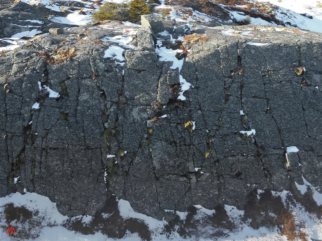
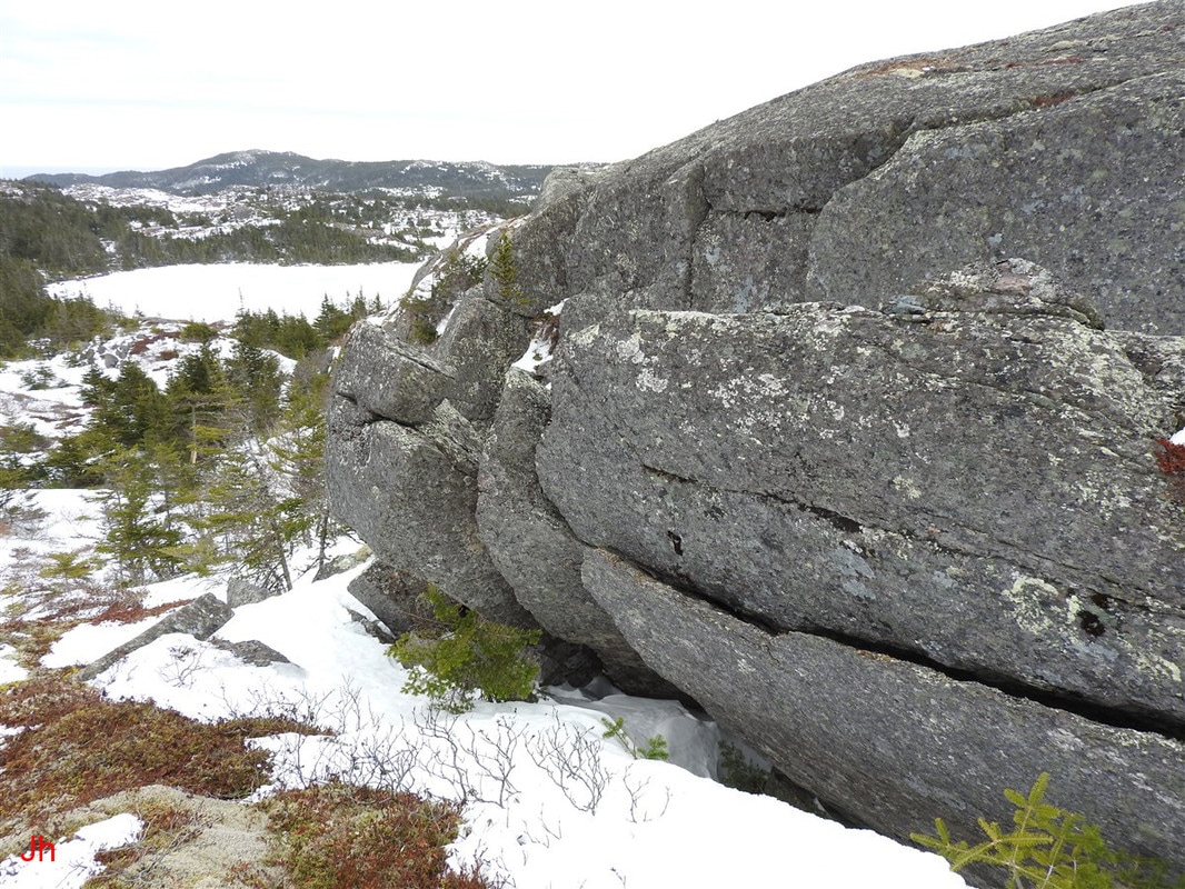
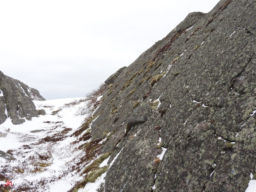
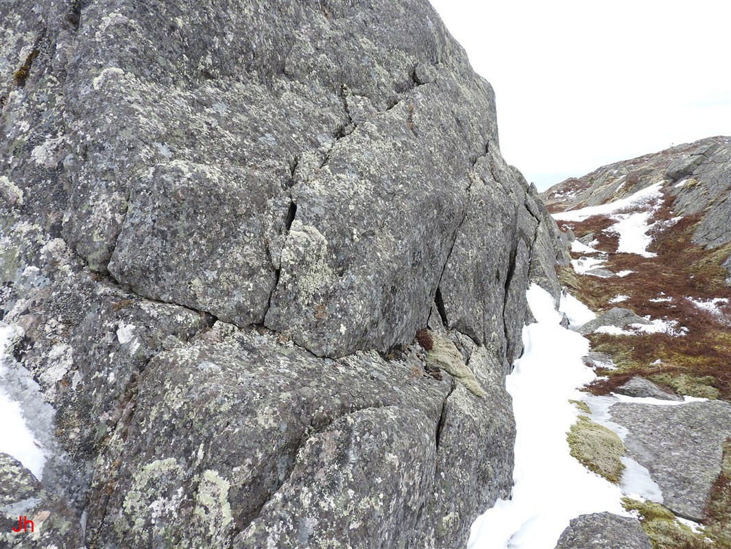
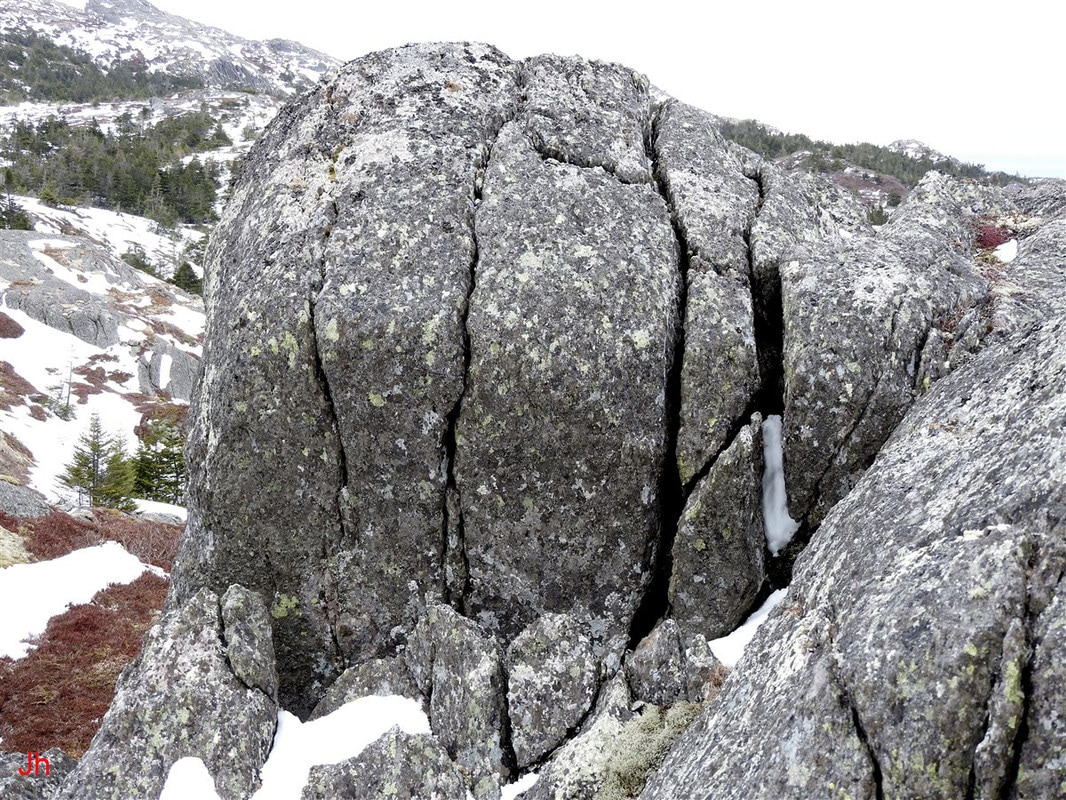
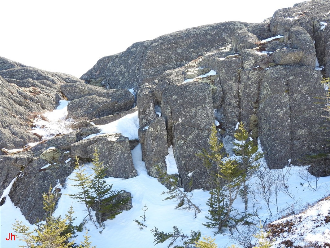
The above photo shows the east wall of the small center valley dividing the ridge, IF-06. This small cliff, about 6 m high runs parallel to longitudinal cleavage and incorporates numerous narrow fissures following the cleavage. The delamination suggests that ice entered the longitudinal joints and widened them by small amounts, typically of the order of a few millimeters to a few centimeters. The widening of the joints led to failure of the outer layers of rock in some cases and these layers spalled off and eventually settled to the ground. The view shown below illustrates the disruption to the glacially-smoothed cliff face caused by spalling.
The area of spalled rock seen in the cliff face above resembles action that might result from freeze thaw weathering in a subaerial environment. However, in the context of the surrounding bedrock disruption seen in the immediate area, it seems more appropriate to link the spalling to subglacial fissure formation and to rock failure directly resulting from the formation of fissures. The photos below show more views of the fissures occurring in the cliff face (G).
Examination of the bedrock disruption features seen in the area of the cliff face (G) suggests that the observed delamination and spalling comprise an example of restricted plucking (see definition in Illustrative Feature 05) in an area where ice motion was severely constrained (see discussion and analysis).
Other bedrock disruption features seen on the ridge, IF-06:
Following is a selection of other frost wedging occurrences on the ridge, IF-06, chosen to help narrow the range of possible explanations for the observations.
Other bedrock disruption features seen on the ridge, IF-06:
Following is a selection of other frost wedging occurrences on the ridge, IF-06, chosen to help narrow the range of possible explanations for the observations.
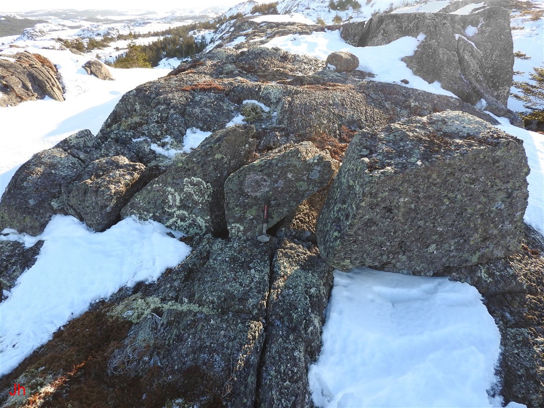
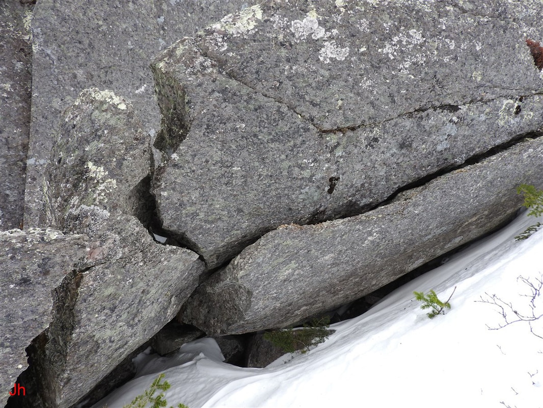
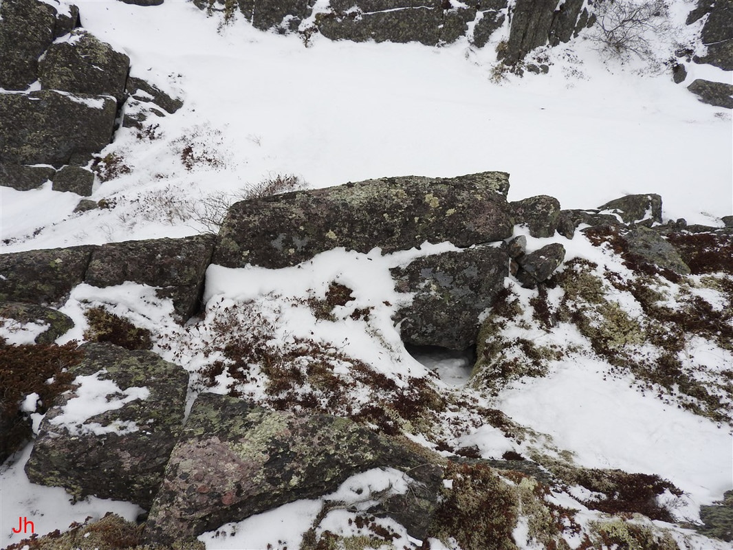
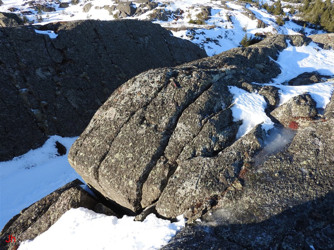
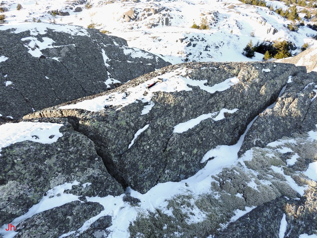
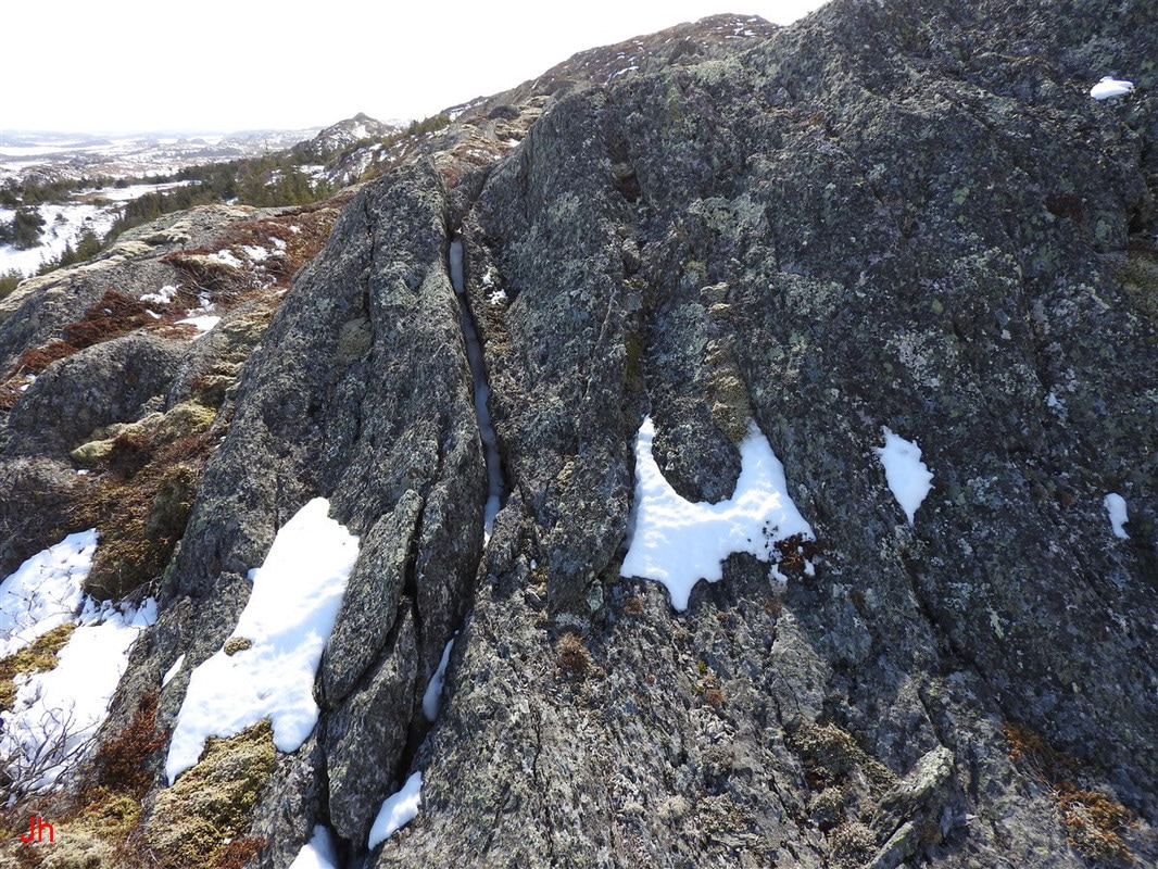
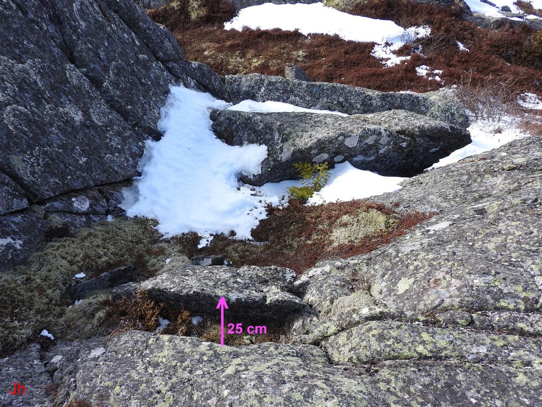
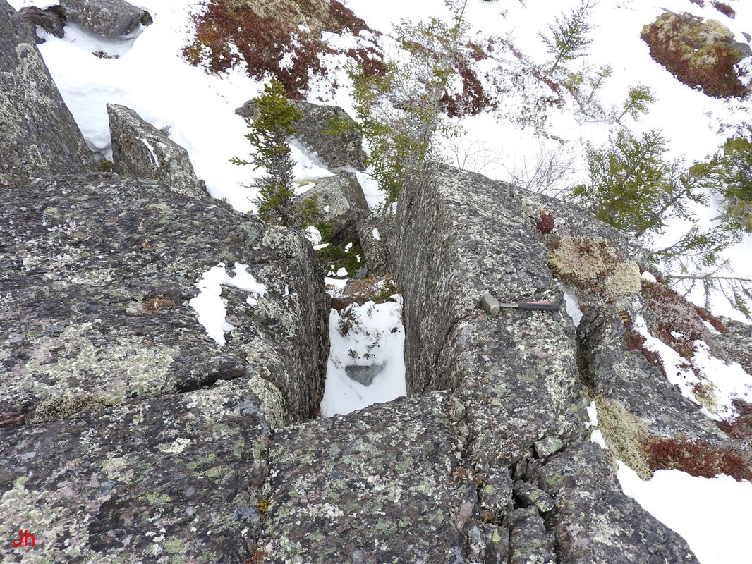
The west-facing rock face on the eastern side of the small valley dividing the ridge, IF-06, is shown above. The large vertical fissure seen in the photo resulted from frost wedging that separated a section of rock from the side of the ridge and shifted it slightly northwest. A view of the shifted section of rock is provided in the photo below.
The above photo shows a large section of rock shifted slightly northwest by ice pressure. This frost-wedging occurrence is one of three large similar occurrences on the ridge, IF-06, (see also feature (C) and feature (F)). Each large frost-wedged rock section was shifted northwest as deep, narrow fissures opened on joints lying south of the shifted section, east of the shifted section or both. The hammer seen near the center of the displaced block in the above photo is 27 cm long.
The photo above was taken with the camera pointing south. The large fissure (5 m long) shown is the result of frost wedging that pushed rock from the east-most side of the ridge, IF-06, eastward. This shift runs counter to the trend whereby most of the large sections of disrupted rock seen on IF-06 have been shifted westward or northwestward. The fissure seen above could be the result of rebound spalling (exfoliation) occurring after glacial loading on the east side of the ridge abated. However, this explanation may not be the preferred explanation in light of other east-directed rock shift features on IF-06 and in the surrounding area. Some of the other eastward-shifted frost-wedge features (for example, the block (D) on IF-06) are clearly not the result of rebound stress.
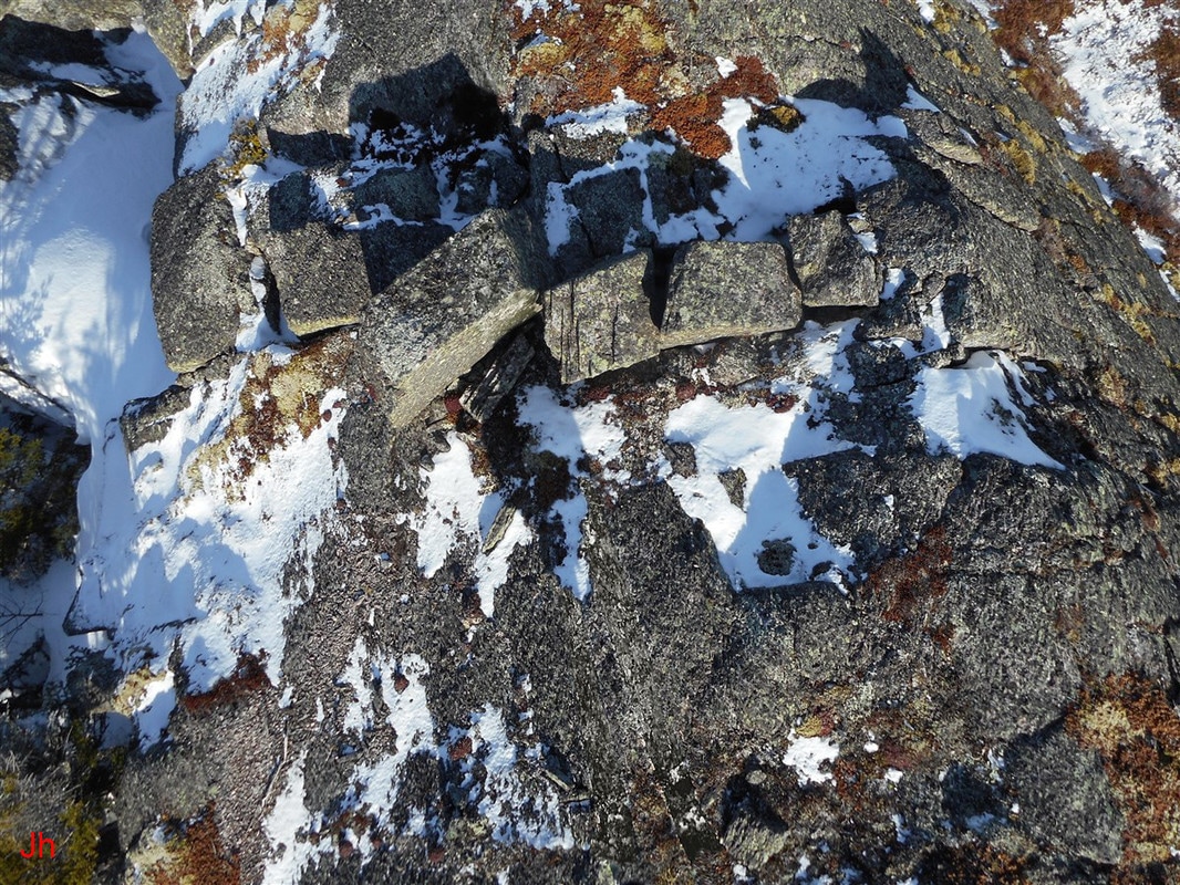
The above southward-looking photo shows the east end of the row of frost-heaved joint blocks (A) (center right) and the east-shifted large block (D) (top center). Just left of center, in the foreground, is a small joint block that has been shifted eastward by ice pressure. An overhead view of this block is seen in the photo below.
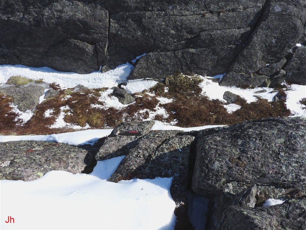
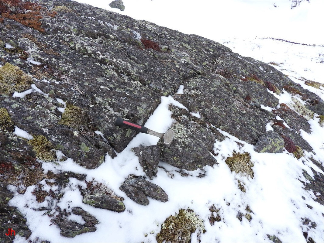
The small block beneath the hammer (27 cm long) has been shifted eastward by ice pressure. In isolation, this feature would be attributed to the action of eastward moving glacial ice. However the above-pictured shifted block lies within 3 meters of blocks in row (A) that have been shifted westward. It is therefore likely that the shift seen above was caused solely by frost wedging. Two more instances of small-scale horizontal frost wedging are shown below.
In the first (left) picture shown above, the indicated shift is toward the west. In the second (right) picture the hammer points in a southerly direction. In the area around IF-06, it is common to see rocks shifted horizontally in a variety of directions. All of these shifts can be attributed to instances where the effects of subglacial frost wedging dominate glacial ice motion (see IF-06 discussion and analysis).
The first (left) photo above shows a view of the frost-heaved block (D). This block lies on the east-facing slope of the small valley dividing the ridge, IF-06, and has been shifted eastward. Directly across the narrow valley is a frost-heaved block on the west-facing slope that has been shifted westward. The west-shifted block can be seen at the top left edge of the first (left) photo and, again, in closeup, in the second (right) photo (block is 80 cm wide). These blocks, separated by about 5 meters, strongly imply that local glacial ice pressure (even if acting through bedrock) did not directly cause both shifts. Rather one or both of the observed rock shifts was caused by frost heave pressure not specifically related to local glacial activity (see discussion and analysis).
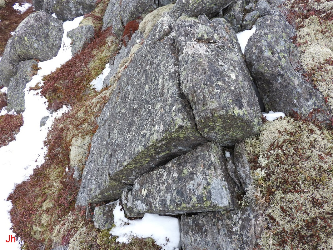
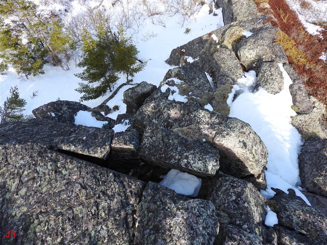
The above picture, taken looking west from a viewpoint at the northwest corner of the ridge, IF-06, shows an instance where a frost-heaved joint block was shifted horizontally until it became completely dislodged. Assuming that the frost heave occurred in a subglacial environment, a low speed of glacial ice movement is indicated because the dislodged block eventually settled at the base of the cliff seen in the picture. The hammer to the left of the slot is 27 cm long and the slot is 1.3 m deep.
The above photo shows a fissure leading to the slot pictured previously. The fissure has been distorted by irregular frost heave along the poorly confined north side-wall. If it is assumed that pressurized ice/water from the fissure was responsible for pushing the west-shifted joint block out of the slot, the ice-pressure damage to the side-wall seems surprisingly mild. However, when considering that the entire process occurred under deep glacial ice, the observations become explainable in terms of a delicate balance of the total ice stress acting on the various surfaces.
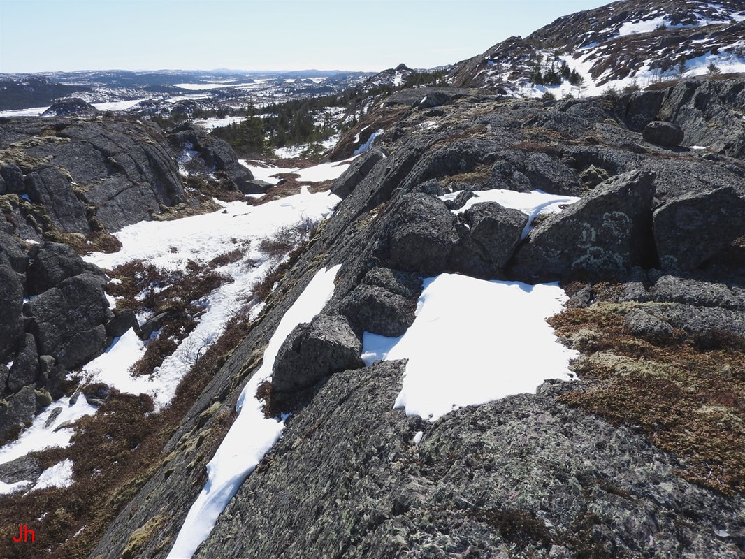
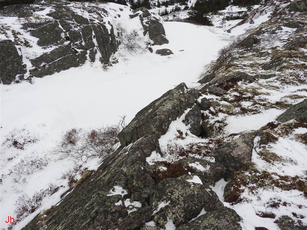
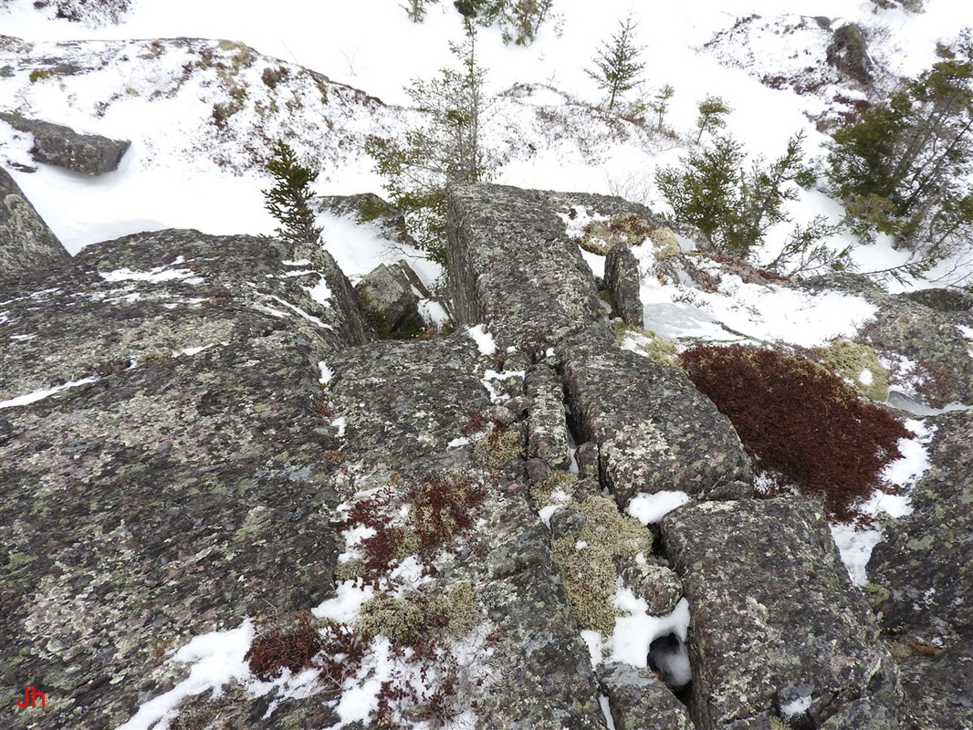
The above photo shows a view looking in an eastward direction at the north end of the ridge, IF-06. Blocks seen near the center of the photo have been shifted northward by ice that entered and widened cross joints. Another view of north-directed frost heave is shown in the photo below.
The above photo shows joint blocks shifted northward at the north end of the ridge IF-06. The fissure containing the snow is about 30 cm wide. The observation that multiple orthogonal surfaces on the ridge, IF-06, experienced frost heave, frost wedging or plucking suggests that pressure from within the ridge may have played a significant role in disrupting the bedrock (see discussion and analysis).
heartofavalonia.org Exploring Geologic History
