| Heart of Avalonia |
Bedrock frost heave with rotation: Part 2
Flow features on level and low-sloping terrain
Flow features on level and low-sloping terrain
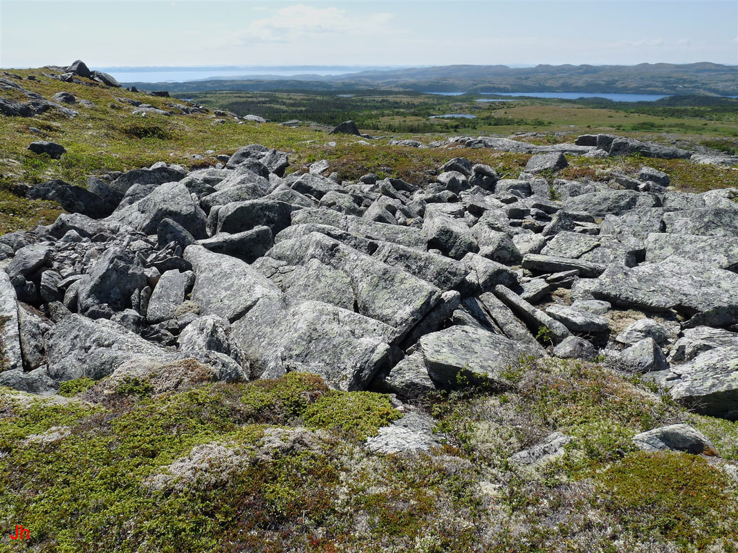
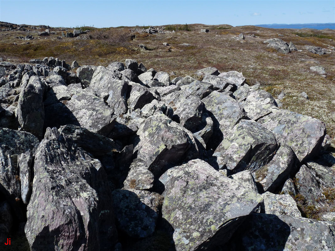
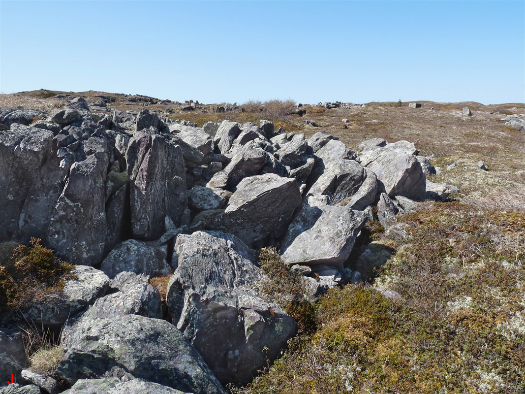
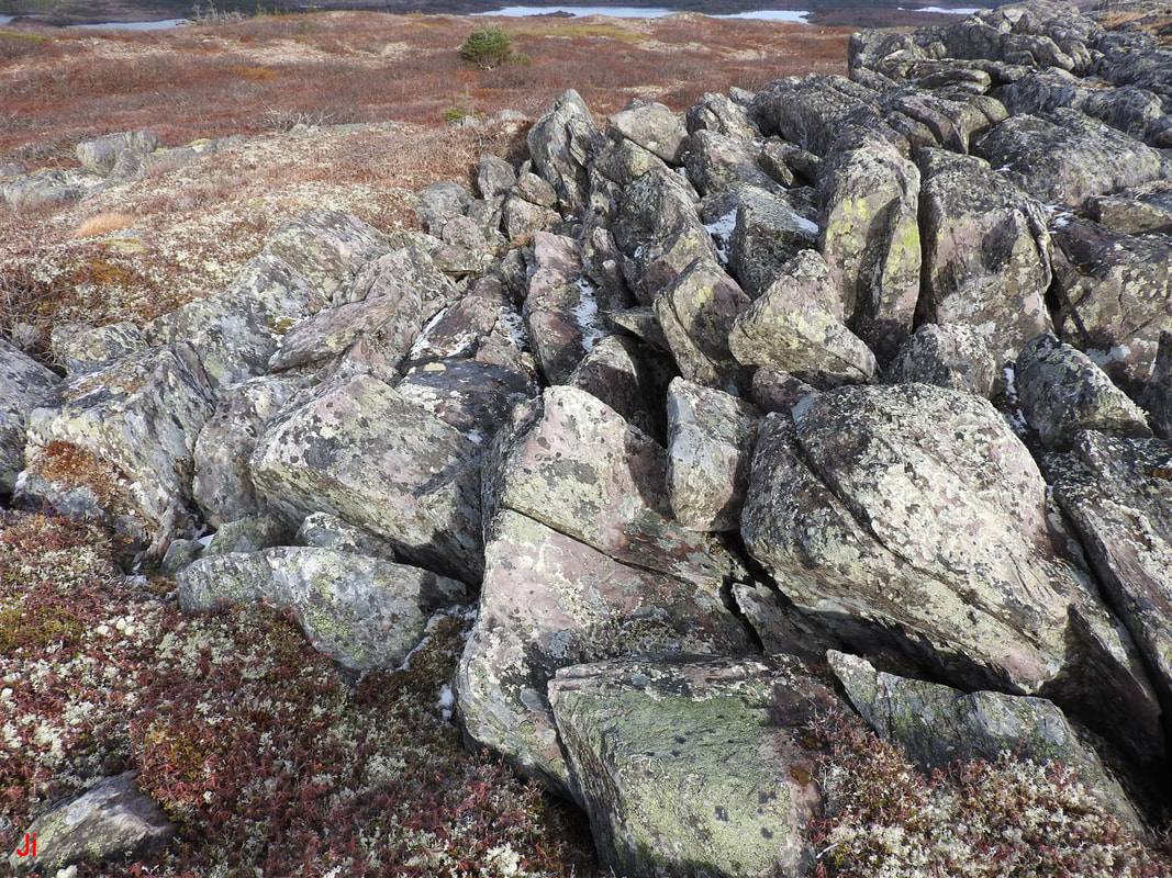
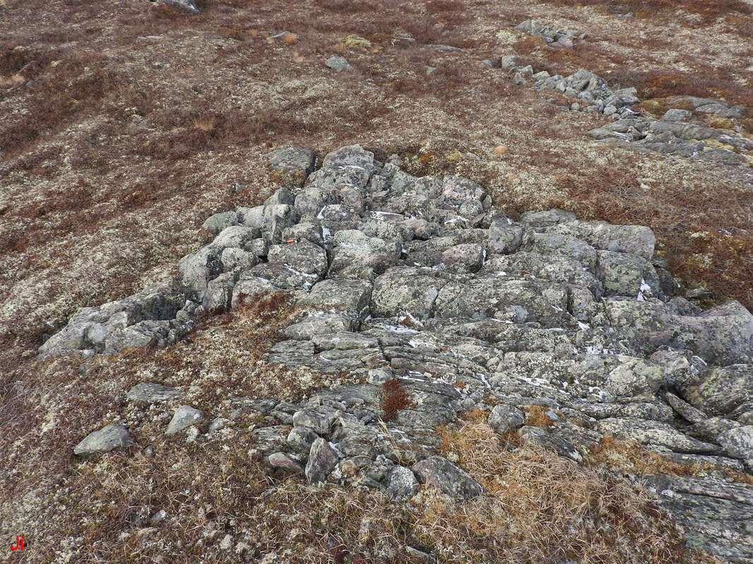
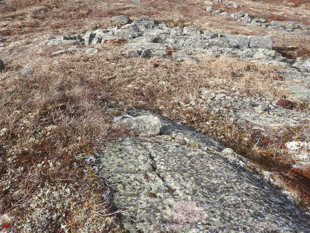
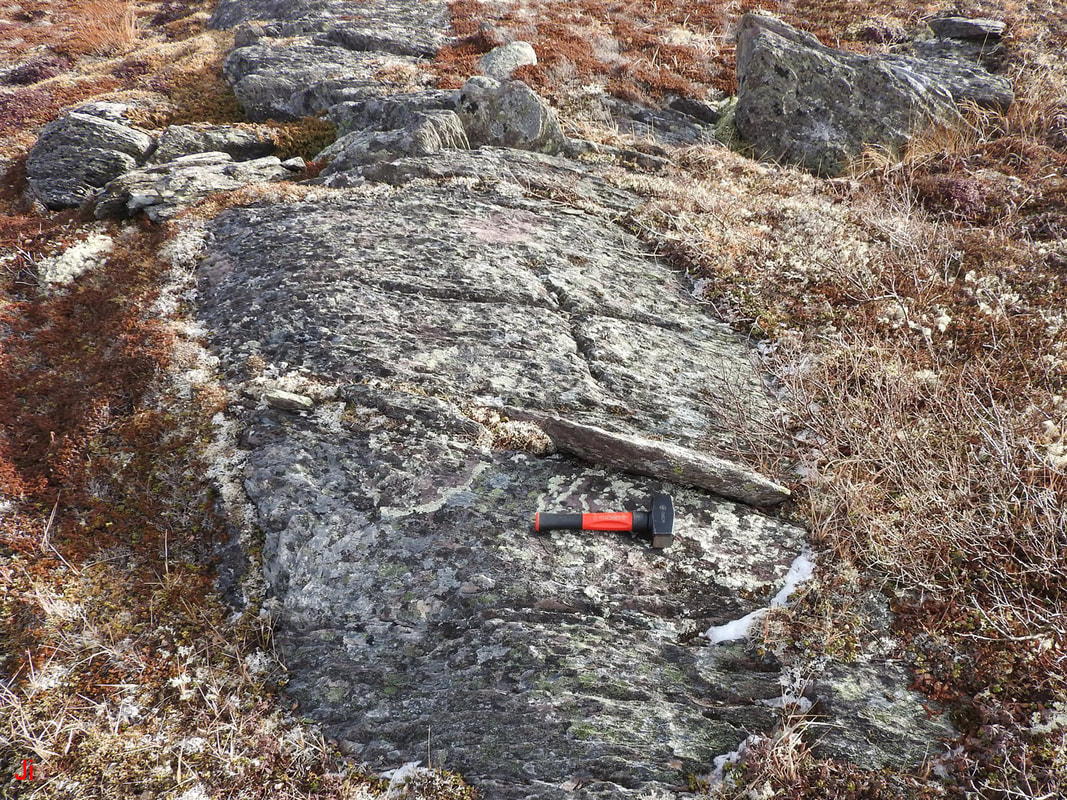
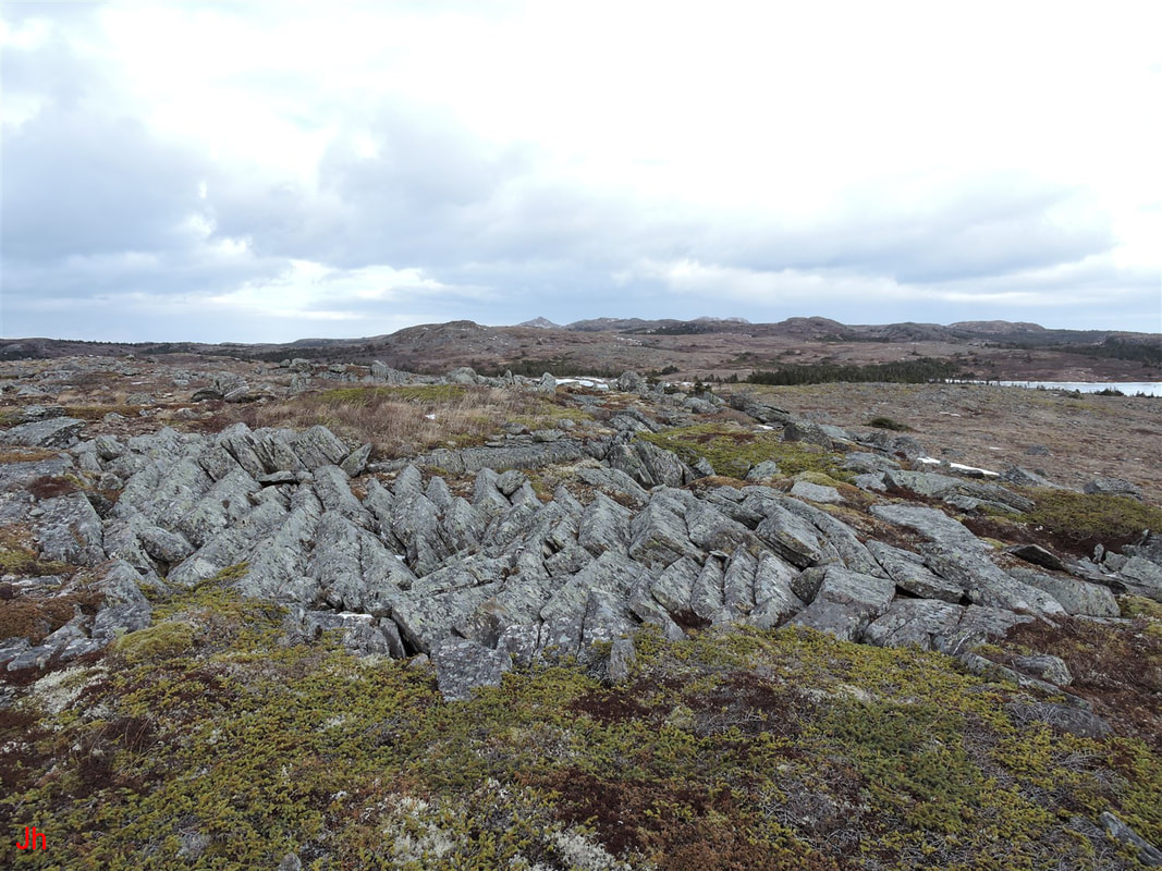
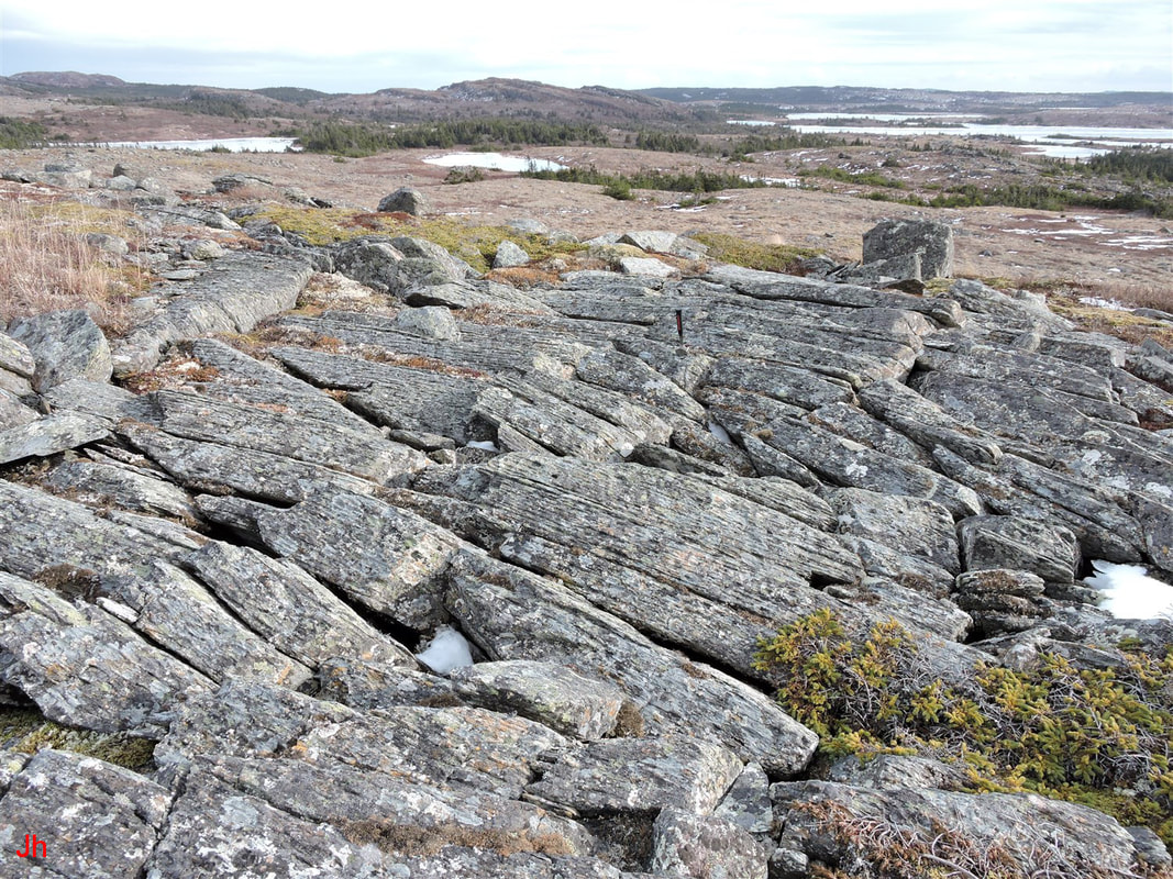
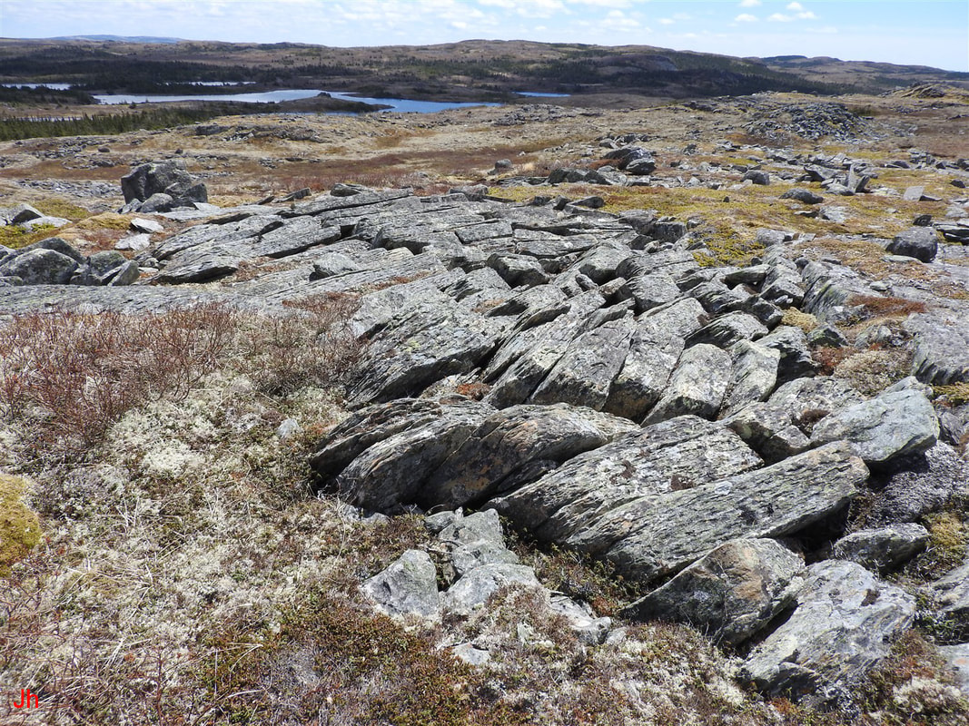
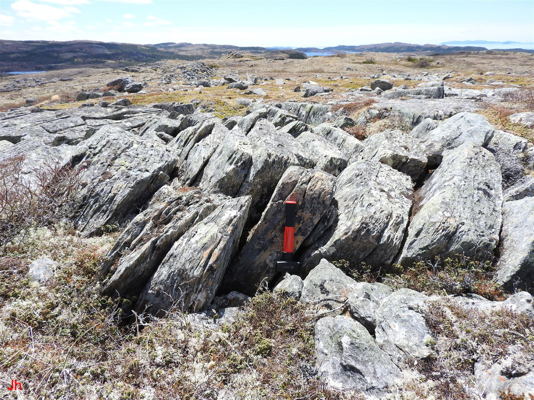
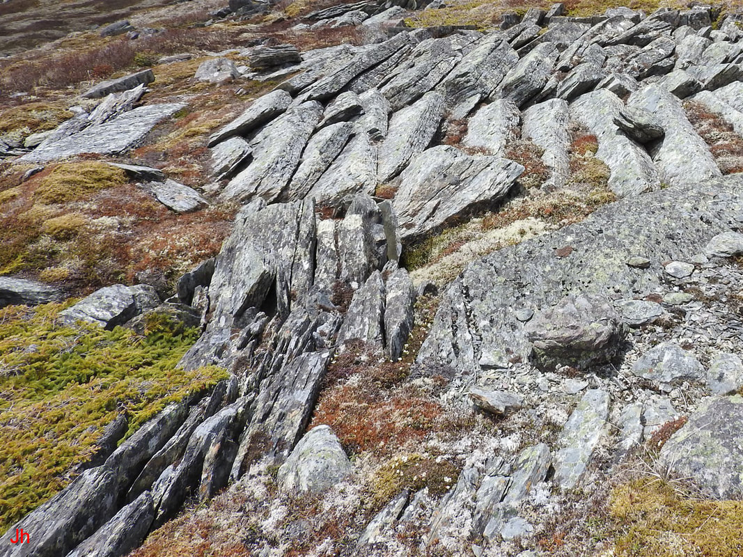
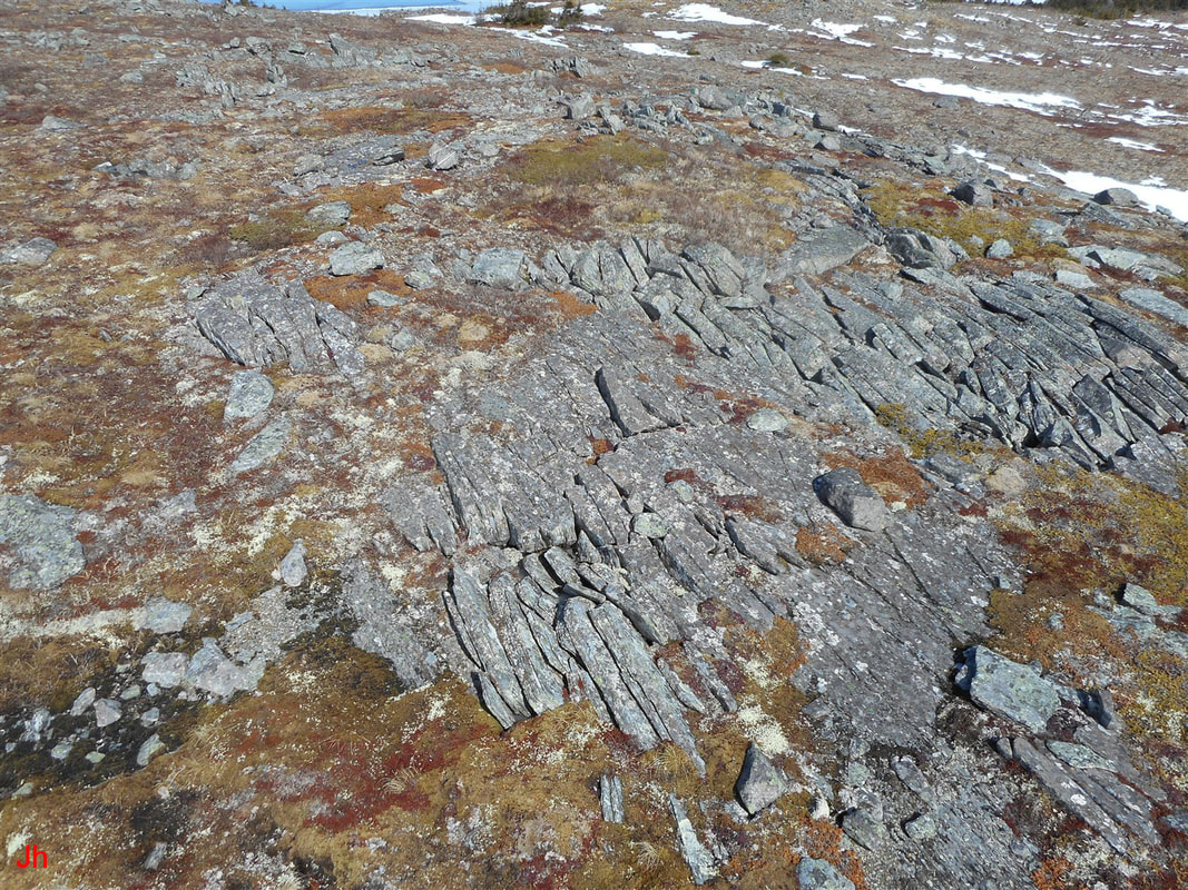
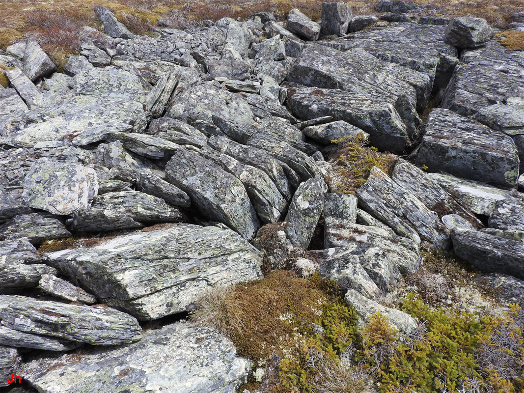
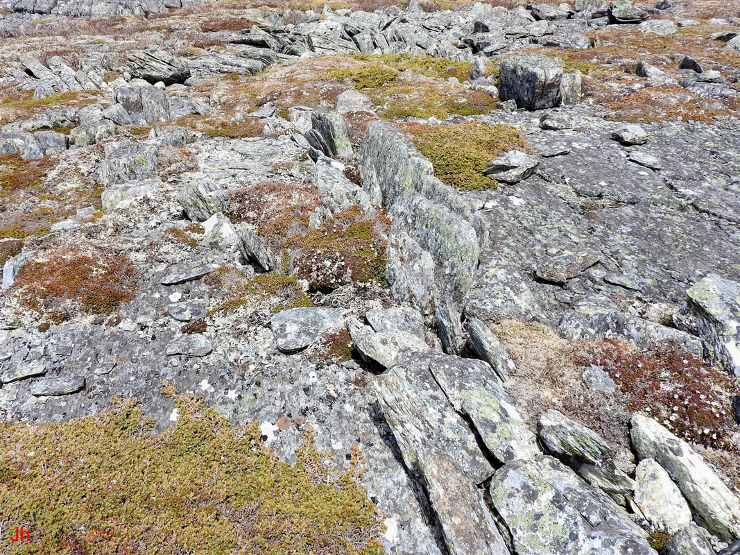
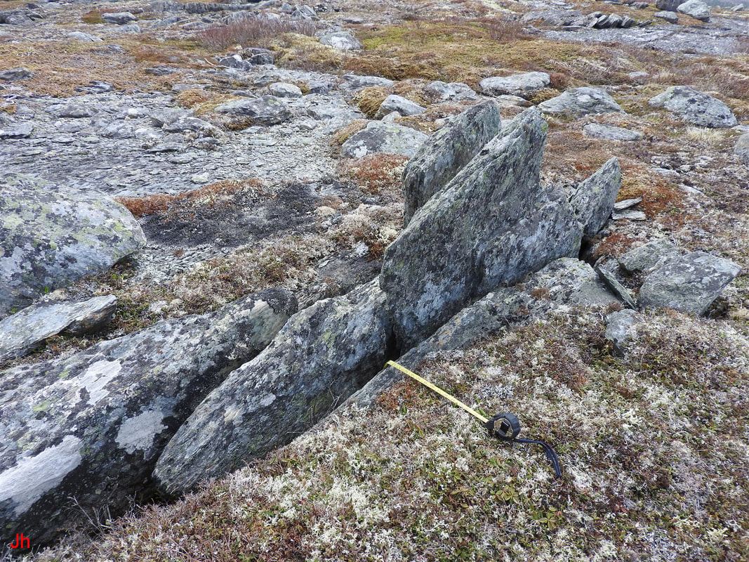
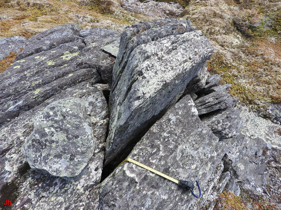
The disrupted-bedrock feature illustrated above shows a layout of rotated blocks sharing a nonrandom angular alignment over a substantial area. An arrangement like this indicates a high probability that the feature was shaped by bulk ice movement occurring tangential to the ground. The feature also incorporates many elements of a frost-heaved bedrock occurrence, and it seems unlikely that glacial ice flow without underlying frost heave would have broken and shifted the bedrock in the manner pictured.
If the above-illustrated feature were observed on the lee side of a glacially-eroded hill, then it might be described as an instance of glacial plucking. On the down-ice side of a hill, a reduction in localized glacial ice pressure would account for the subsurface intrusion of ice needed to drive joint blocks into a moving ice stream. However, on a level surface the conventional mechanics and thermodynamics of glacial plucking fail unless the pressure disrupting the bedrock is assumed to be intrinsic to the local hydrogeology. In addition to this assumption regarding pressure, which forms part of the Subglacial Ice Plume model, the overlying glacier must necessarily be deemed cold based so as to trap artesian groundwater and remove heat of crystallization.
Rotated bedrock frost-heave features showing strong evidence of modification by glacial ice flow can appropriately be termed flow features because they provide a record of past cold-based glacial flow, preserved in the layout of bedrock fragments aligned by ice creep.
Many instances of bedrock disruption and bedrock displacement are seen on the Avalon Peninsula, occurring on the presumed down-ice slopes of ice-eroded hills and ridges. These instances can superficially be described as glacially plucked features. Undoubtedly, plucking by warm-based glaciers has contributed significantly to establishing the glacial geomorphology presently observed on the Avalon. However, it is not reasonable to assume that every down-slope bedrock-disruption feature is the sole result of warm-based glacial plucking. Many of the "plucked" features show characteristics more in common with "flow features" as defined above. A hybrid model seems appropriate in such instances. Warm-based glacial plucking sets the stage and subglacial frost wedging under cold-based ice sculpts the result.
Four examples of flow features on level and low-sloping terrain are provided below. These examples can help to illustrate potential links between three processes:
1) Plucking (usually attributed to warm-based glaciation) as seen on the down-ice (lee) sides of hills and ridges.
2) Down-slope bedrock disruption incorporating joint-block rotation that apparently occurred under cold-based glacial conditions.
3) Formation of bedrock frost heave monoliths, clusters of monoliths and other related vertically-oriented bedrock disruption features, often seen on low-sloping terrain.
At several locations on the Avalon Peninsula, the three processes appear to be integrally associated and inseparable.
Flow features:
Example 1
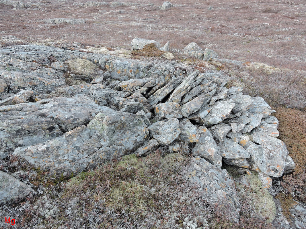
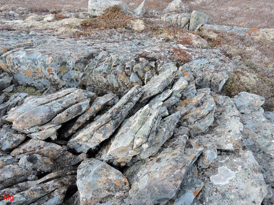
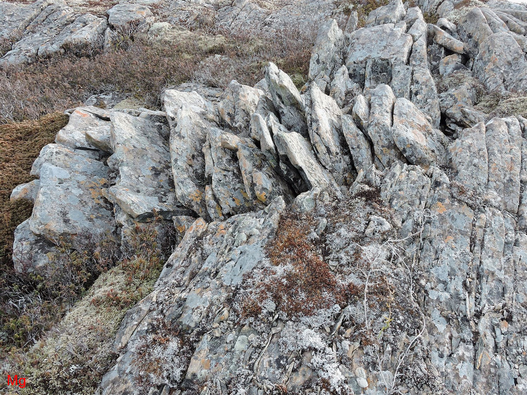
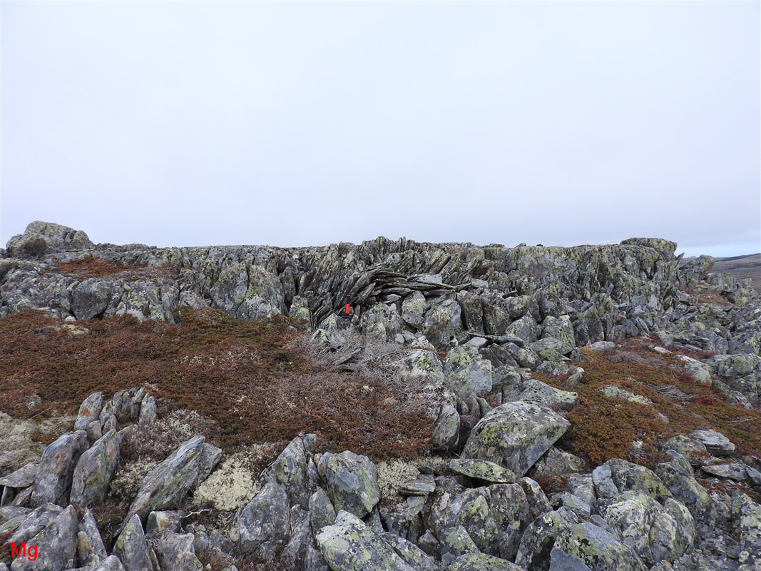
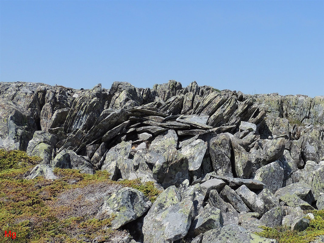
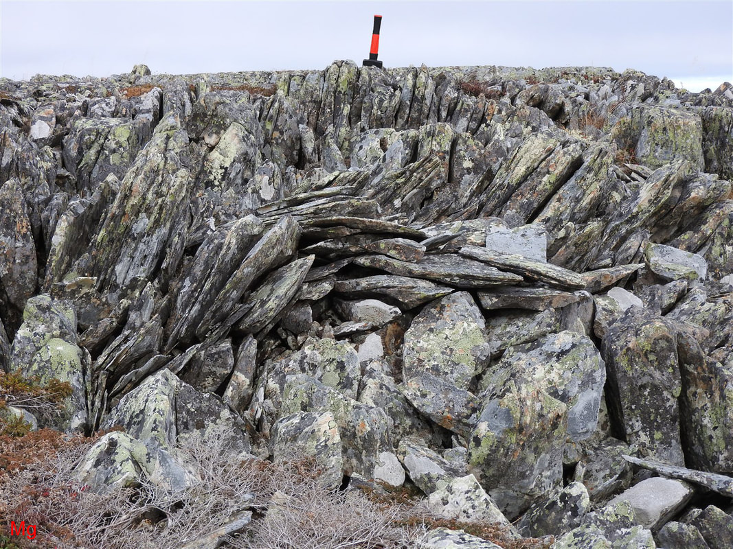
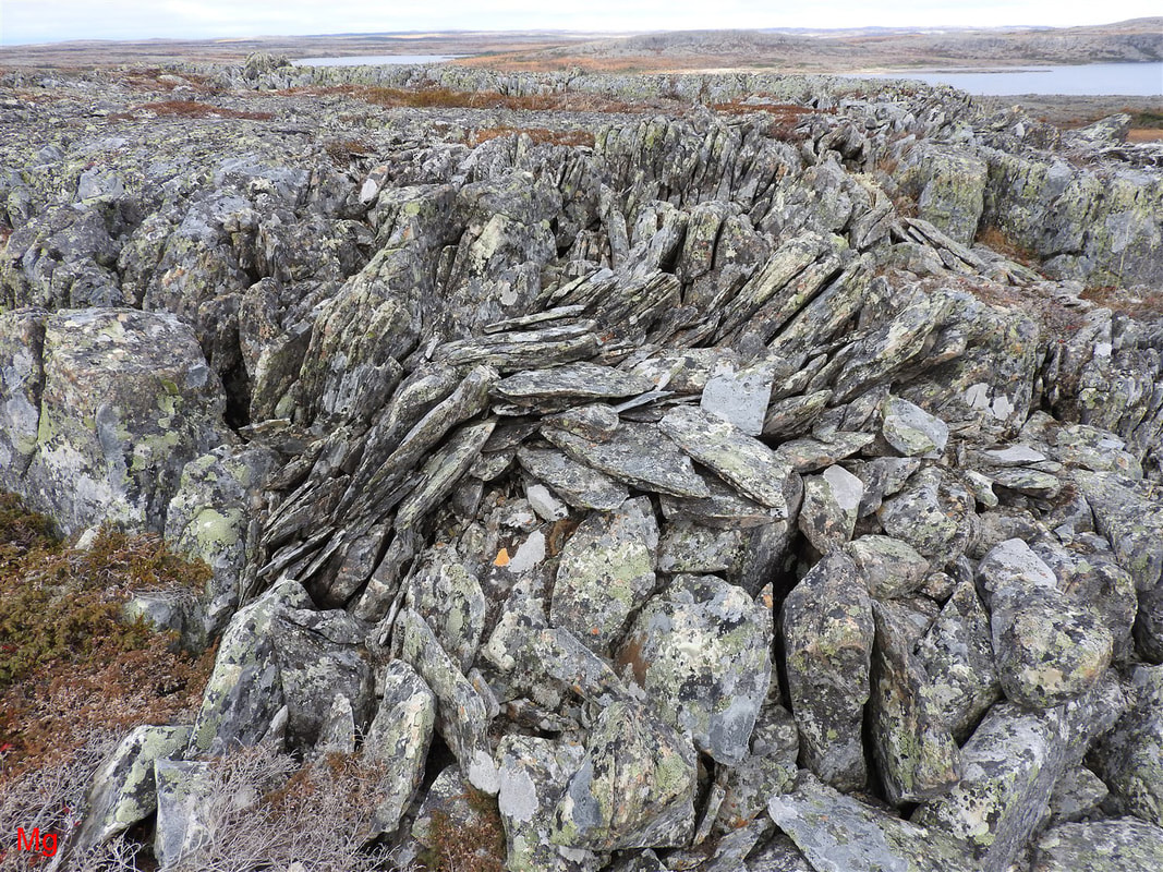
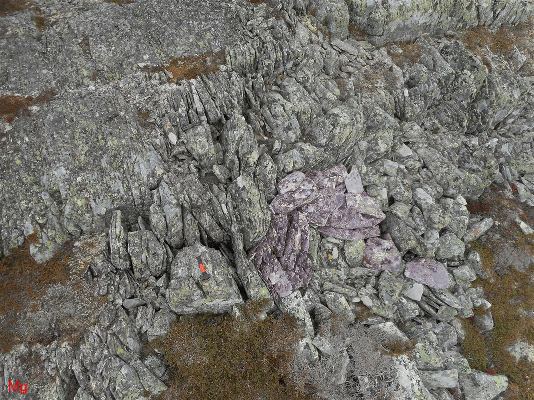
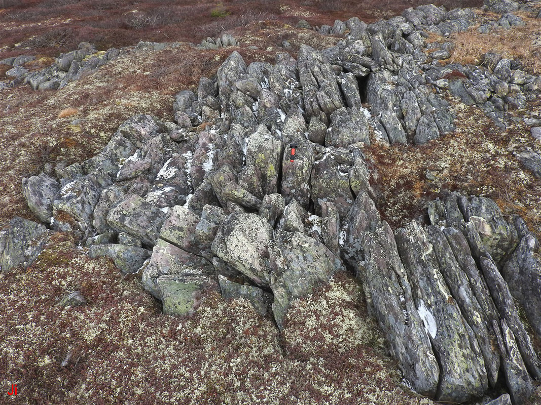
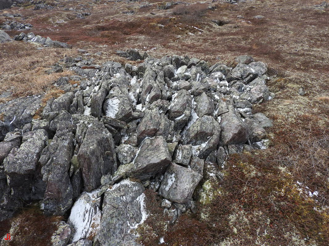
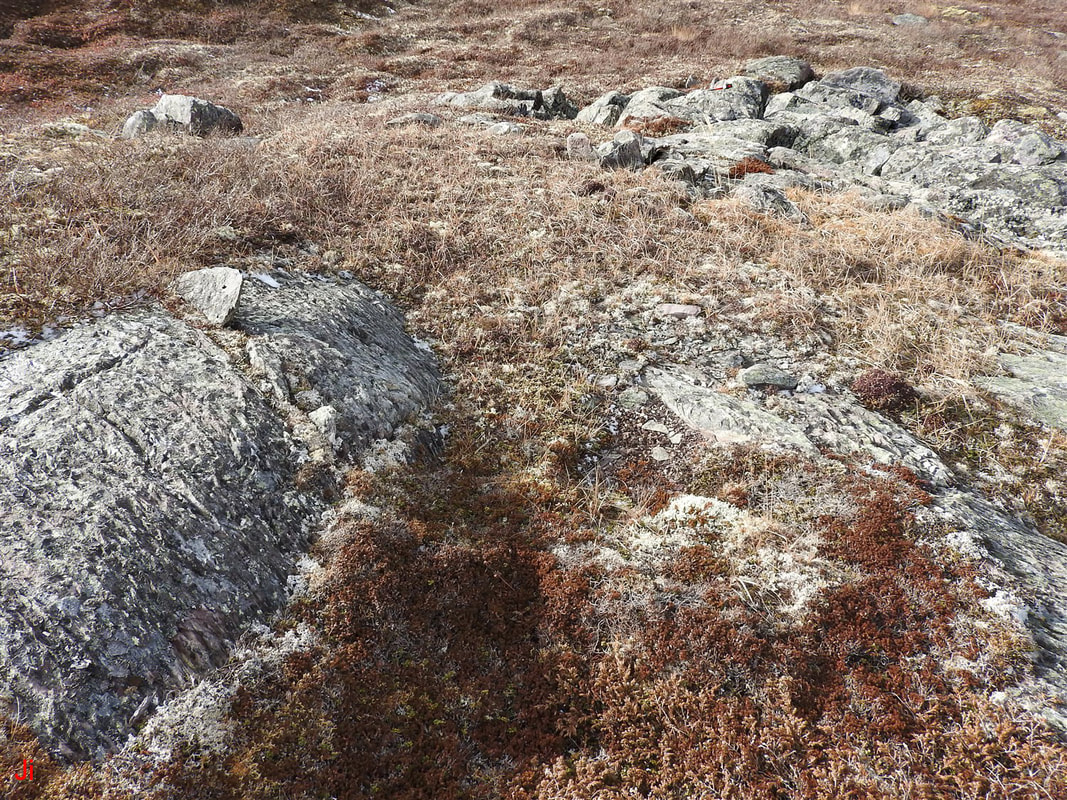
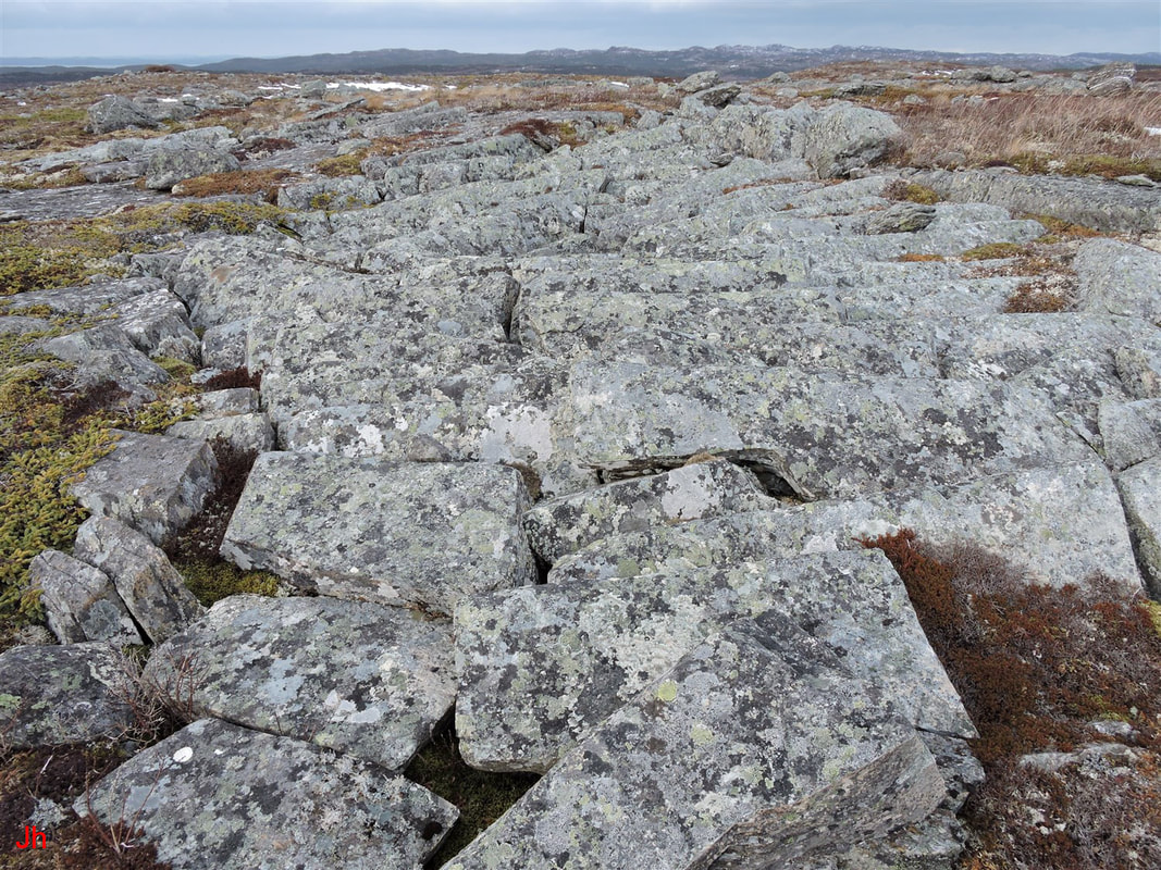
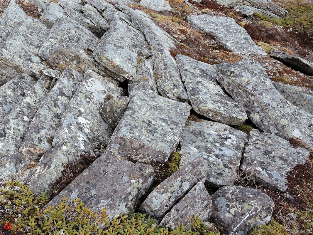
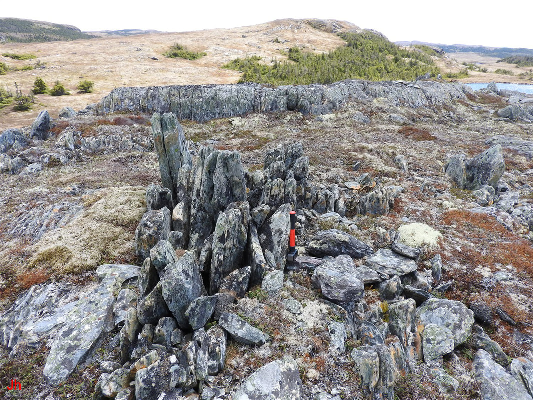
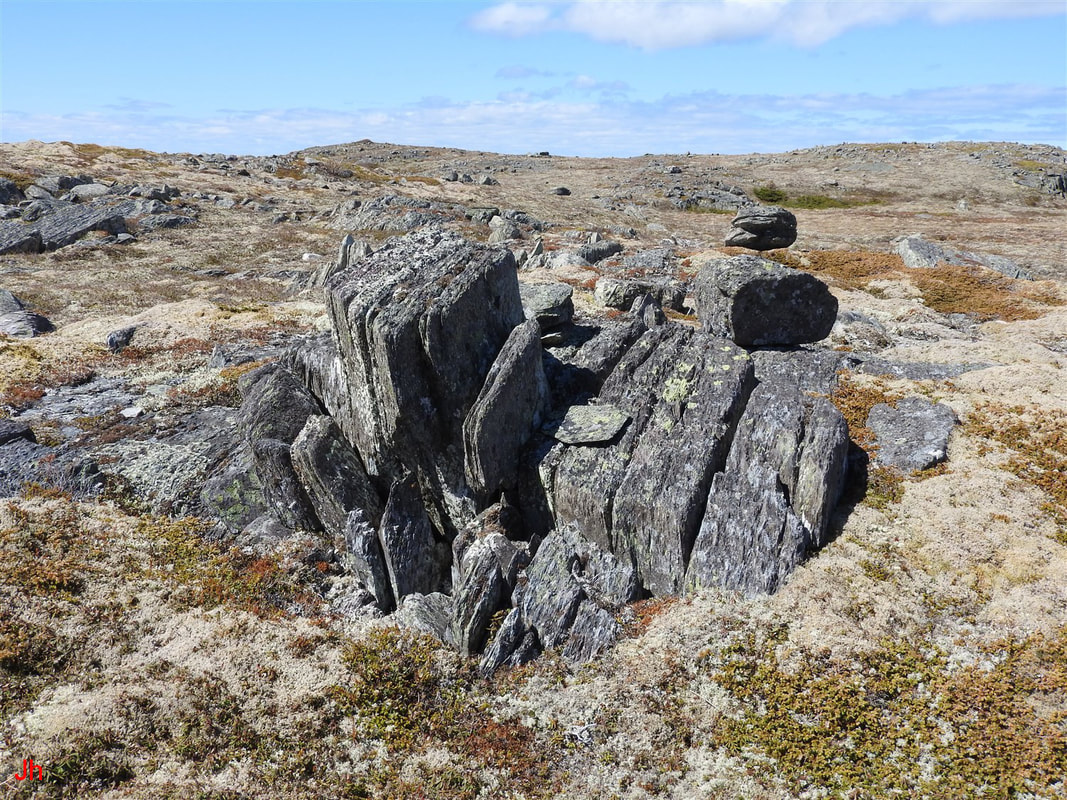
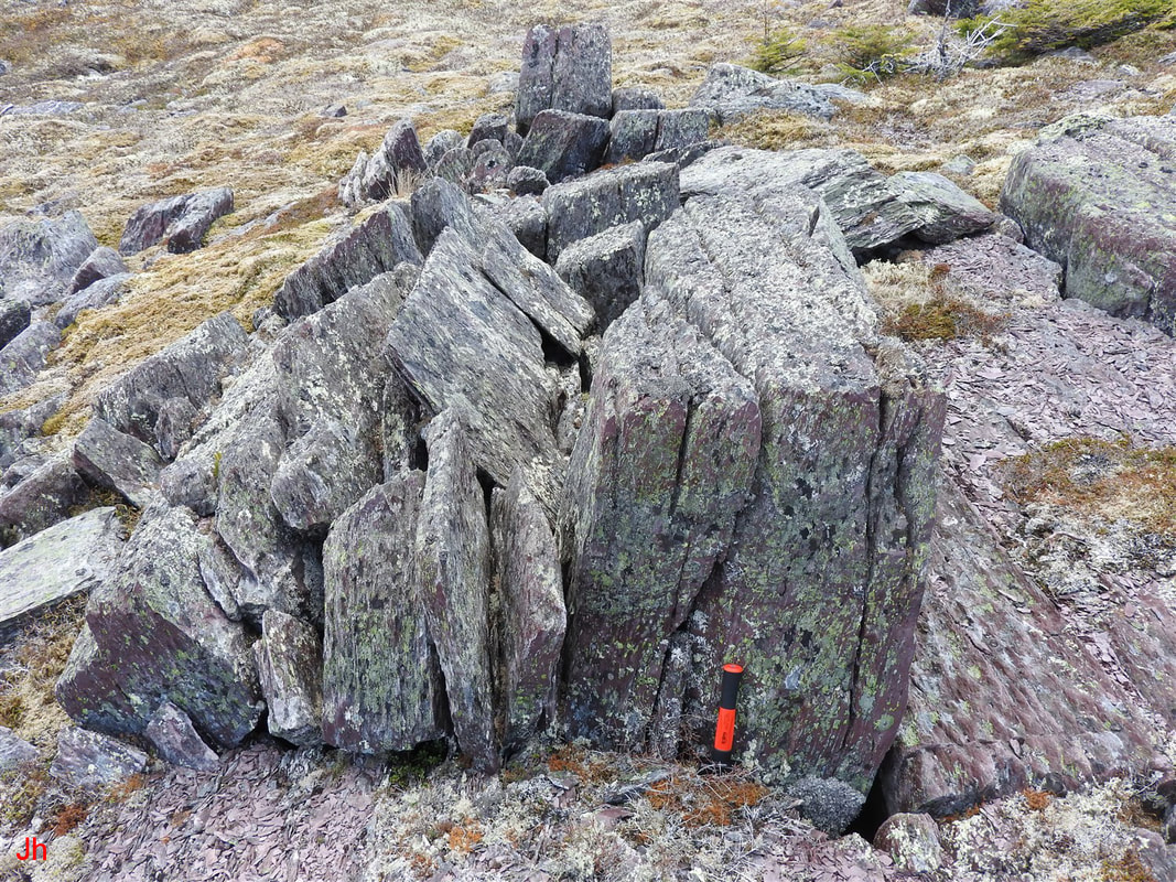
This small flow feature (about 3 m across) occurs in an area characterized by severe ice-disrupted bedrock and abundant frost-heaved monoliths. The aligned and rotated fragments indicate the probable action of overlying glacial ice moving left to right (direction as shown in photo) via creep. Two closeups of the feature are shown below.
Although the feature occurs on the end of a small ridge and there is an accompanying drop in elevation, the layout of the blocks seems unlikely to have resulted solely from the mechanical action of a glacier (either warm-based or cold-based) moving downhill over a bedrock edge. Rather, the feature shows indications of vertically-directed bedrock frost heave and concurrent or subsequent alignment of blocks by both glacial action and settling.
Example 2
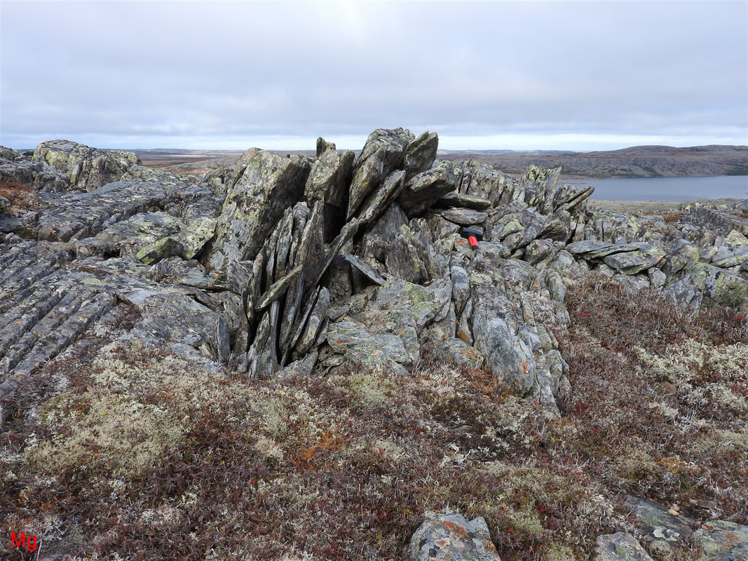
The small flow feature shown in the above three photos was apparently formed by subglacial bedrock frost heave that drove fragments upward into ice moving left to right (direction as shown in above photos). Settling played a significant role in shaping the final result. Before departure of overlying ice allowed the fragments to settle, it is likely that the rock comprising the feature extended upward at a steep angle, reaching a peak height substantially above the surrounding ice-disrupted bedrock. A horizontal component of creep motion in the overlying ice caused step-wise shear failure in the protruding monolith, making it vulnerable to disintegration upon departure of the surrounding ice. Two views looking downward onto the flow feature are shown below.
In the second overhead view shown above, fragments comprising the flow feature were tinted with a magenta shade to help differentiate them from the surrounding rock. Note that many nearby joint blocks in the highly ice-disrupted bedrock outcrop are deflected in the same direction as is the flow feature. Further confirmation of ice flow in the indicated left-to-right direction along the ridge is provided by the rotations of nearby frost-heaved bedrock fragments shown in the following photo.
The above photo shows a similar, but less well developed flow feature on the same ridge and about 30 m away from the main flow feature illustrated in the previous photos.
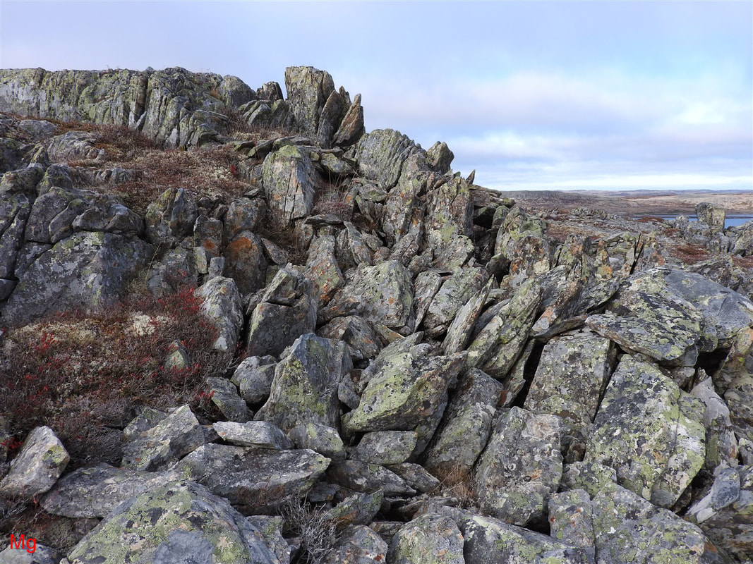
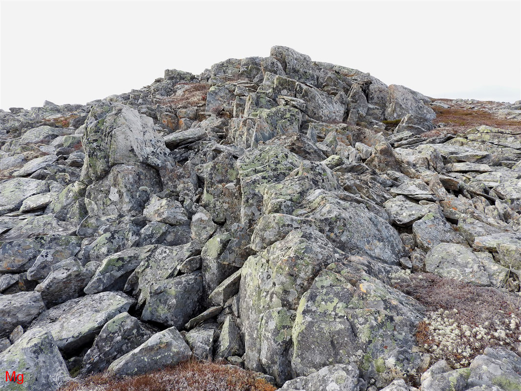
The down-ice (lee) end of the ridge, shown in part at the extreme right of the first photo for this Example 2 and in the two photos below, has been disrupted by ice action in a manner somewhat resembling glacial plucking.
The down-ice (lee) end of the ridge, shown in part at the extreme right of the first photo for this Example 2 and in the two photos below, has been disrupted by ice action in a manner somewhat resembling glacial plucking.
The ice-disrupted bedrock seen at the down-ice end of the ridge hosting the flow feature (Example 2) suggests that a process resembling glacial plucking occurred at the end of this ridge. However, the bedrock fragments remain significantly organized and it is not evident that much bedrock was transported away from the site by glacial action. It seems likely that the indicated "plucking" was caused by a cold-based glacier moving in creep and that the severity of bedrock disruption reflects both the elevated hydraulic pressure intrinsic to local bedrock hydrogeology and the reduced hydrostatic pressure that characterizes the glacial environment downstream of an obstruction.
Example 3
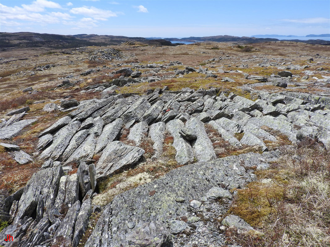
The above photo shows a moderately-sized flow feature on terrain sloping gently downward toward the upper right (direction as seen in photo). Although a glimpse of Placentia Bay can be seen in the right-hand background, and the apparent ice flow across the feature was directed roughly toward the nearest stretch of Placentia Bay coastline, other ice flow indicators in the immediate area are contradictory. Specifically, the land behind the above-illustrated feature (land that lies to the left of the view shown) crests and begins to slope downward in the opposite direction. Significant rotated frost-heave features less than 100 m away from the above-pictured feature, but on the opposing slope, are oriented so as to indicate ice flow in a direction reverse to that indicated above (hence away from Placentia Bay). Large frost-heaved bedrock monoliths are present on top of the ridge. The ridge at this site was apparently a source of glacial ice during the interval when the frost-heave features (including the flow feature, Example 3) were formed.
In the above photo of the flow feature (Example 3) it is evident that bedrock disruption commences as a system of fissures before grading over into rotated joint blocks. A question arises as to whether the feature could have originated from a protruding bedrock formation that was not lifted by frost heave, but rather was fragmented and shifted solely by the mechanical action of an overlying moving glacier, perhaps a cold-based glacier. Examination of the above scene indicated that several individual blocks in the assembly appeared to be frost-heaved, jacked above nearby bedrock and underlain by cavities. The following photo, taken from the other side of the feature shows further indications of frost heave.
In the above photo, exposed bedrock is seen in the left foreground (partially snow covered and including a fissure), while blocks nearby appear to have been raised relative to the height of this bedrock. Note also the joint block (center foreground) shifted out of line with the preceding block (seen just to the left). This side-deflected block appears to be a frost-heaved joint block that was ejected from substrate and then shifted by ice emanating from within the group of blocks. The generally chaotic arrangement of loose fragments seen scattered among the larger, more organized joint blocks is also suggestive of frost heave activity and ascending ice having occurred within the formation. Side-on views of the feature are shown below.
The above photos emphasize that, in overall appearance, the flow feature (Example 3) resembles an area of ice-disrupted bedrock possessing a significant vertical component of rock displacement. Although glacial ice moving tangential to the surface of the feature dominated the shifts and rotations of the underlying blocks, it seems that the process causing the observed bedrock disruption has also included a significant component of non-tangential ice motion.
Two views along the ice path leading toward and across the flow feature (Example 3) are shown above. For scale, note the hammer (hard to see) appearing in the center left of the flow feature (visible in both photos). The second (right) photo shows a stretch of exposed bedrock hosting a small fragment of frost-heaved bedrock protruding upward. A closeup of this frost-heaved fragment is shown below.
The above-pictured frost-heaved fragment (beside the hammer) is significant because its presence precludes glacial ice movement via basal sliding at any time after the fragment was placed. Note also, two other occurrences of frost-heaved bedrock visible in the background (a small block rotated and sheared into three sections seen on the left, a larger block seen on the right). The photo below shows that the fragment seen above near the hammer is rotated in the direction conforming with the rotations of the large blocks comprising the flow feature (Example 3).
Although the direction of rotation of the small frost-heaved fragment seen above might have been coincidental, it is reasonable to deduce that the rotation would relate to the same episode of ice movement that caused large-scale block rotation in the downstream flow feature (Example 3). If this deduction is valid, then the small frost-heave feature is a subglacial feature and the associated ice movement was by creep only.
Example 4
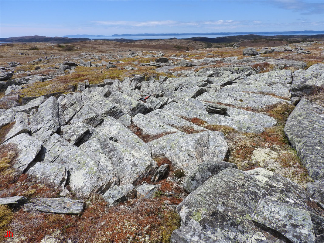
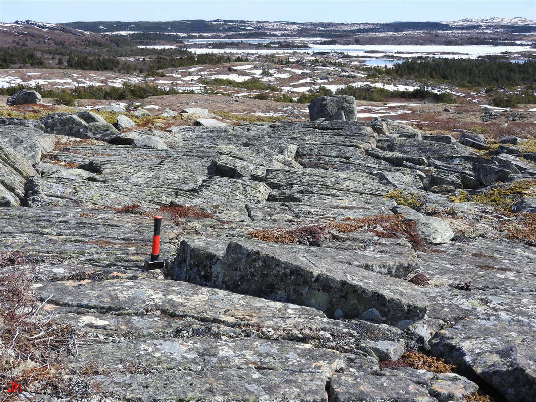
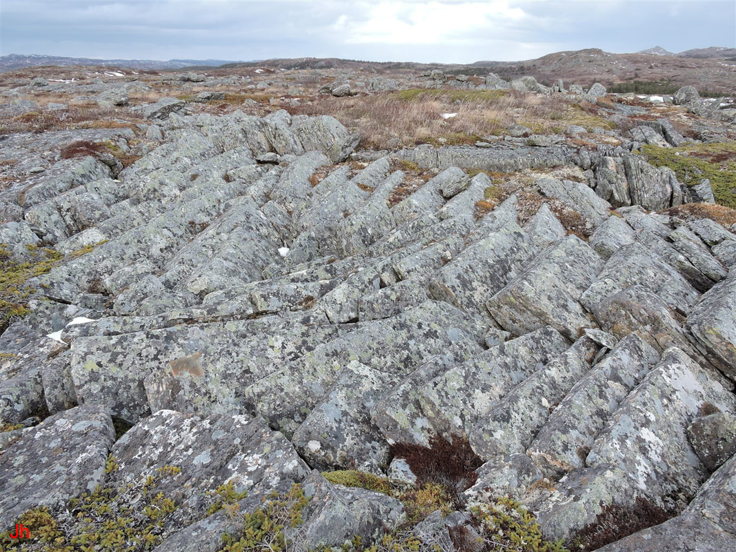
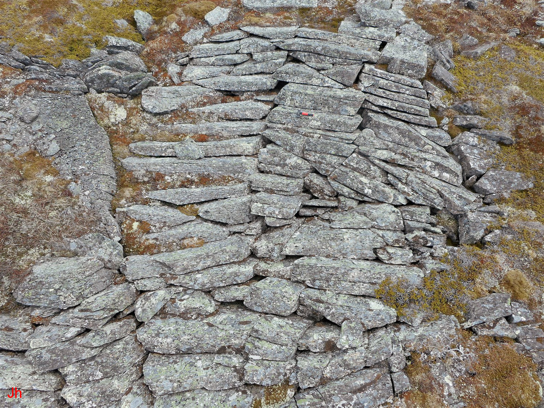
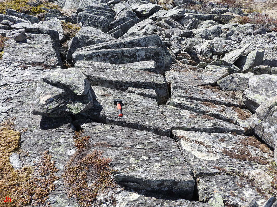
The above-pictured large flow feature occurs on terrain sloping gently upward along the indicated ice path (right to left, as seen in photo). This feature is well organized and strongly suggestive of a subglacial origin.
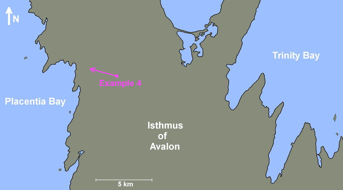
The above map shows the location of the flow feature (Example 4), marked with a magenta dot. The arrow does not show ice flow direction (this was not well determined from independent evidence), but rather, shows the normal to the top edges of the tipped blocks comprising the flow feature, projected onto the horizontal.
The ocean seen in the background of the above photo is Placentia Bay and this bay was the likely end point for glacial ice moving across the foreground landscape. The most direct route to the coast from the camera position lies approximately along the view direction seen above. Ice therefore probably crossed the foreground landscape at an angle oblique to the alignment of the blocks seen in the picture. The block alignment is controlled more by foliation (the top edges of the blocks are tectonically aligned) than by ice flow direction.
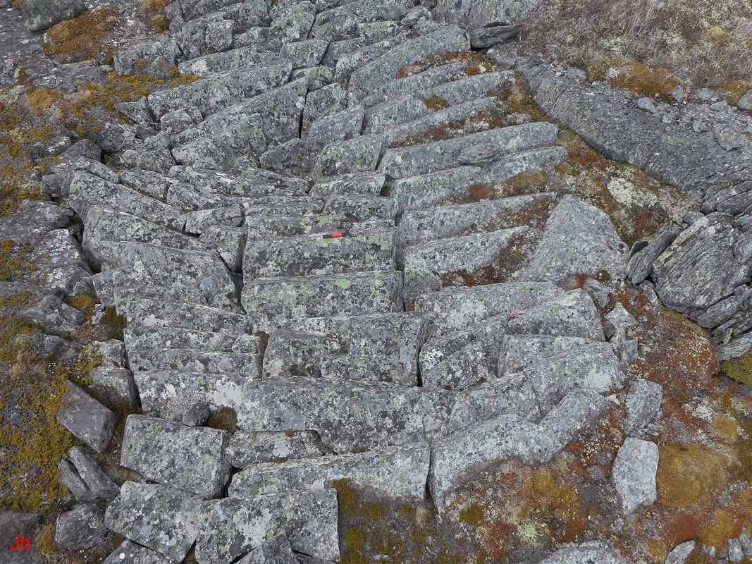
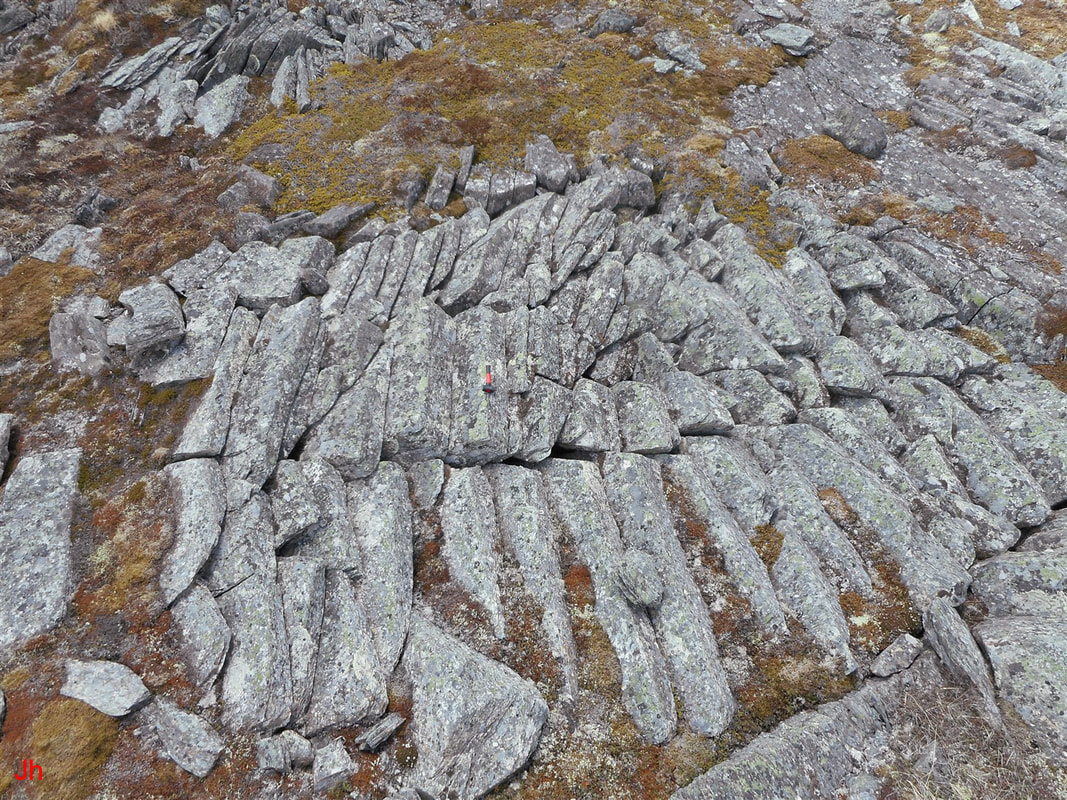
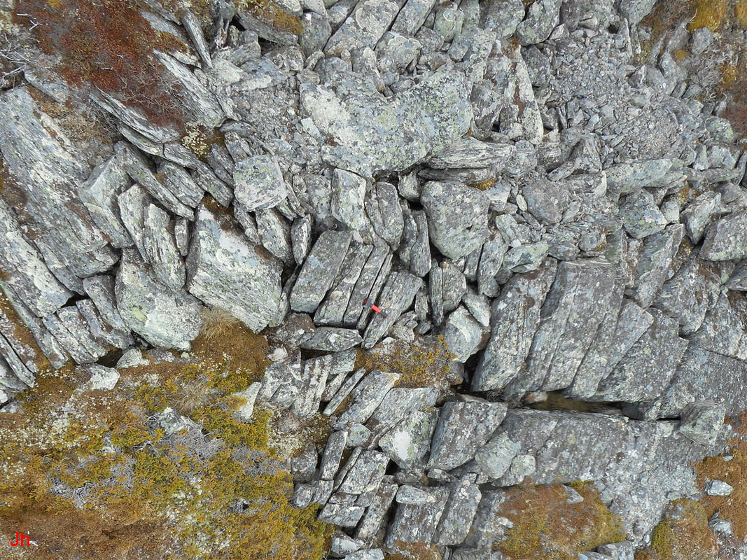
Two overhead views of the highly organized flow feature are shown above. For scale, a hammer can be seen at the center of both photos.
The landscape up-ice from from the flow feature (Example 4) is shown in the background of the above photo. The flow feature is located on the up-ice side of a ridge making glacial plucking an improbable explanation for its origin. The rock seen roughly centered at the back of the feature is an erratic and is unrelated to the flow feature. The foreground rock is bedrock with minor frost-heave. More views of the feature, from several different directions, are shown below.
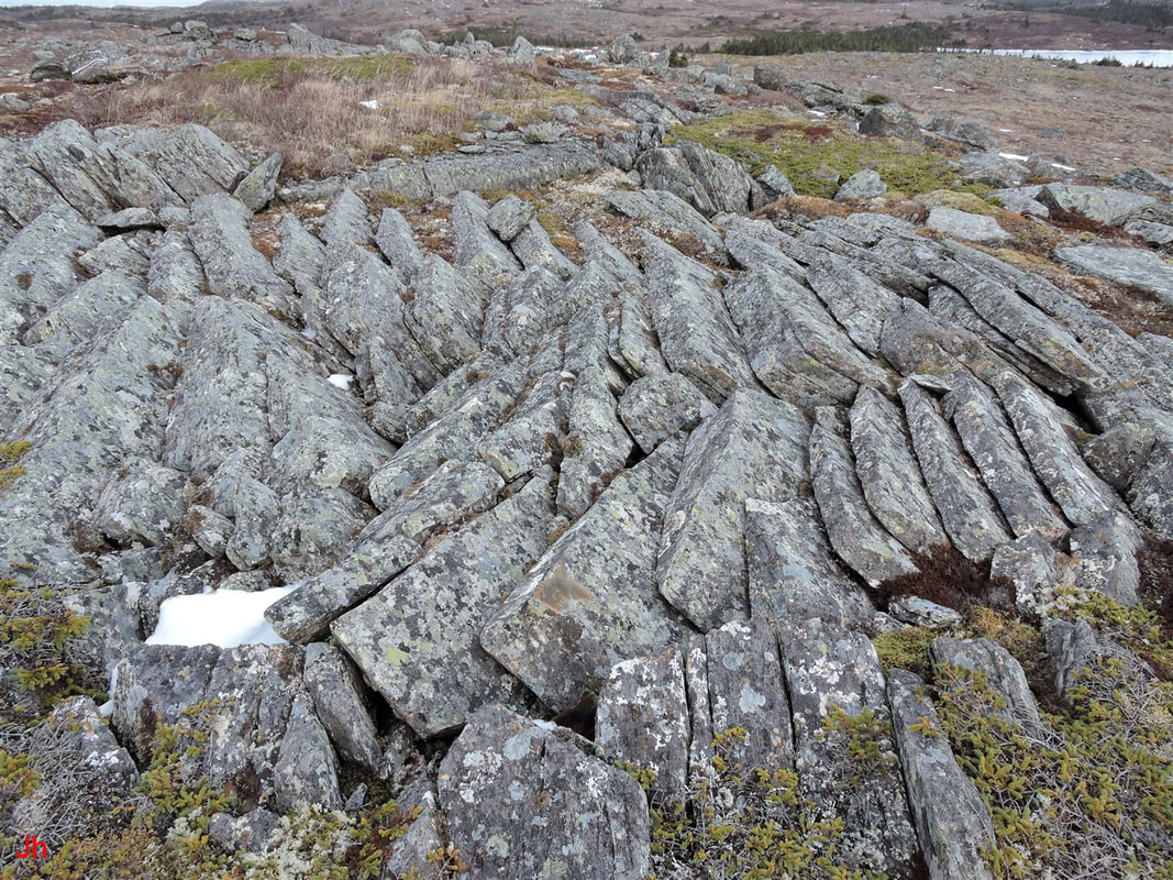
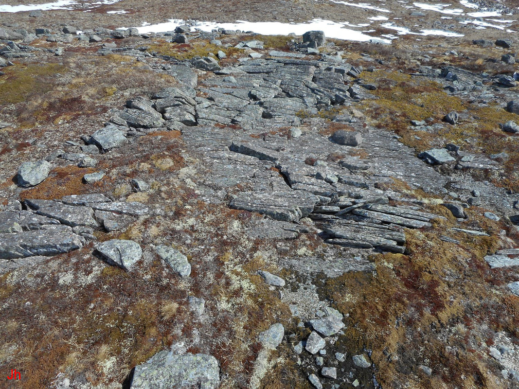
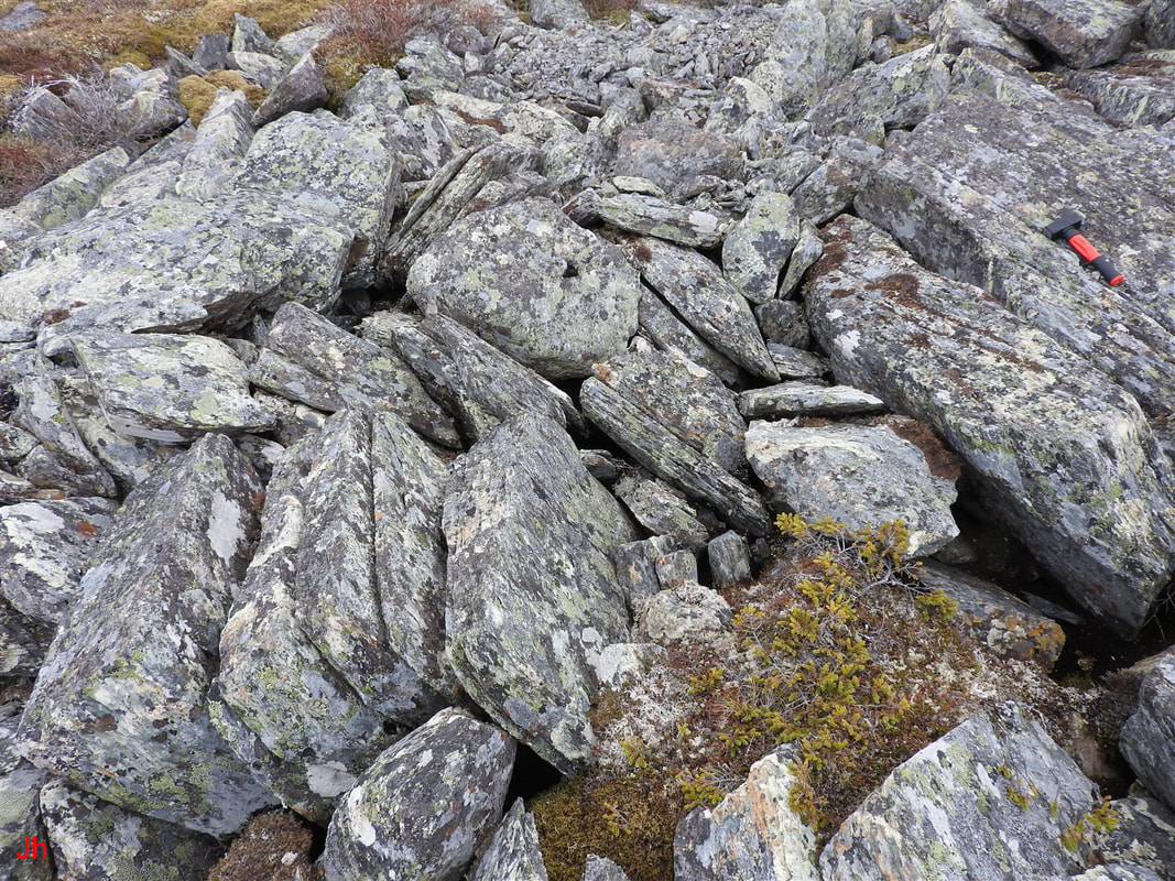
As illustrated in the above photos, the flow feature (Example 4) is an assembly of contiguous rotated joint blocks apparently derived from a single unit of bedrock. The rotation was forced by horizontally-directed ice loading and the deformation of the bedrock in response to the load was by step-wise shear failure. The shear failure occurred along planes of tectonically-induced foliation. There was also rock failure along cross joints which allowed adjacent rows of blocks to shear at slightly different rates and to experience small amounts of differential rotation about a vertical axis. In addition to step-wise shear, there was evidence of horizontal translation of some blocks. This can be seen in the photos below.
Sheared blocks seen in the left foreground of the first (left) photo and, again, in the right foreground of the second (right) photo have been translated horizontally sufficiently to separate them.
As with the previously described flow feature (Example 3), there remains a question as to whether subglacial bedrock frost heave was instrumental in triggering the bedrock disruption or whether the disruption could have been the sole result of tangential glacial action loading a protruding unit of intact bedrock. Answering the question requires an examination of both the flow feature (Example 4) and the surrounding area.
As with the previously described flow feature (Example 3), there remains a question as to whether subglacial bedrock frost heave was instrumental in triggering the bedrock disruption or whether the disruption could have been the sole result of tangential glacial action loading a protruding unit of intact bedrock. Answering the question requires an examination of both the flow feature (Example 4) and the surrounding area.
The average height of the blocks comprising the flow feature (Example 4) does not significantly exceed the height of the surrounding land. In the first (left) photo above, it is evident that the blocks extend downward into the ground at least as much as they extend upward above ground level. The second (right) photo shows bedrock (center, right) with adjacent blocks not reaching above ground level as defined by the adjacent bedrock. If the feature was originally an intact block of raised bedrock, then the average level of the top surface of the disrupted feature would remain elevated above ground level following disruption of the rock by glacial mechanical action.
The above view from an overhead vantage point shows the flow feature (Example 4) and adjacent bedrock (seen on left side of frame). A small area of frost-heaved bedrock, where the blocks have not been rotated, is visible at the top left of the frame (closeup photos of these blocks are included in the discussion below). The bedrock frost heave evident in these blocks might have postdated the glacial flow that shaped the majority of the feature. Alternatively, sharp spatial variations could have existed in near-ground ice creep patterns. The area of bedrock seen at the left gives way to a group of rotated frost-heaved blocks visible in the left foreground. These rotated frost-heaved blocks appear to comprise an ice-disrupted extension of the preceding (up-ice) section of less-disrupted bedrock. Note the irregular fissure traversing the frame from top to bottom and comprising the right-hand edge of the area of less-disrupted bedrock. It can be argued that some of the blocks in the flow feature (Example 4) have been displaced laterally (toward the right) by ground-ice pressure acting outward (toward the right) from the fissure. The sideways shift occurs primarily in the area where the fissure passes to the right of the less-disrupted bedrock.
For purposes of comparison with the above observations, another nearby example of laterally-directed bedrock displacement is shown below.
For purposes of comparison with the above observations, another nearby example of laterally-directed bedrock displacement is shown below.
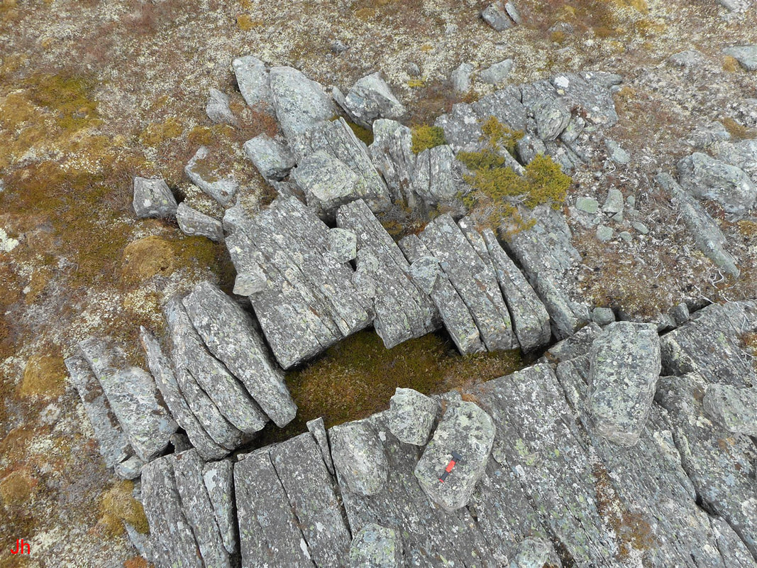
The ice-disrupted bedrock feature shown above illustrates sideways-displaced blocks of bedrock at a location about 30 m away from the boundary of the flow feature (Example 4). As with some blocks in the flow feature (Example 4), the blocks shown above appear to have been displaced horizontally by ice pressure emanating from a fissure that presumably originated as a cross joint in the longitudinally-foliated bedrock. It is likely that the frost-wedging action leading to displacement of the blocks shown above occurred in a subglacial environment. The displacement of the blocks is at right angles to the ice flow direction indicated by joint block rotation in the local area. Note the two rotated joint blocks seen in the lower left of the photo. The rotation of these blocks aligns with the rotation of the blocks in the flow feature (Example 4).
Another view of the flow feature (Example 4) similar to the overhead view presented previously, but taken from a lower angle, is shown above. It appears likely that the glacially-modified feature (Example 4) originated in a subglacial bedrock frost heave event that left a large number of closely-spaced blocks in an elevated configuration where they were vulnerable to rotation by cold-based glacial ice moving horizontally in creep across the site. The frost heave and the deflection by glacial ice might have occurred simultaneously or else in close succession. The lateral displacement of some blocks reflects a horizontal manifestation of the same ground-ice pressure that caused the vertical component of frost heave evident in the flow feature (Example 4) and nearby.
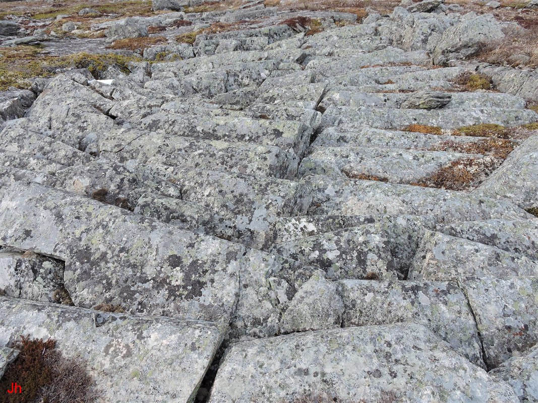
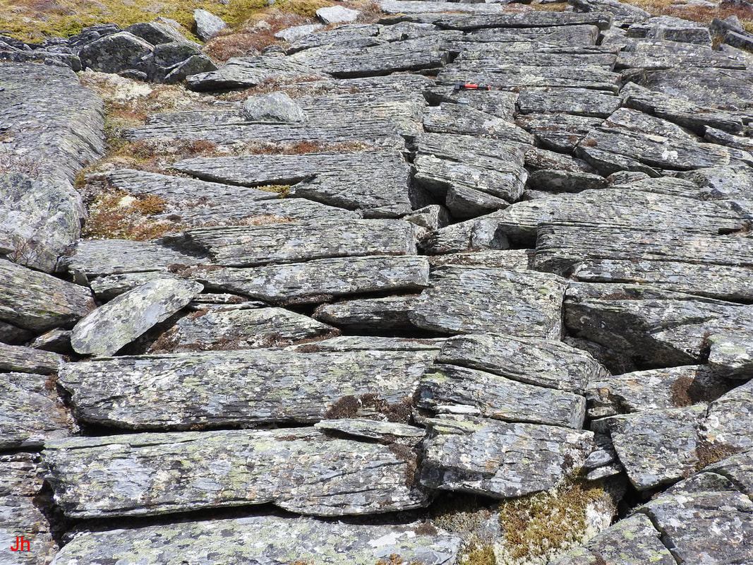
Foliation in individual joint blocks is clearly visible in the above photo, where the blocks show a distinct laminated appearance. This well-delineated foliation would normally be deemed to reflect primarily the tectonic history (regional metamorphism) of the rock. There is little doubt that the foliation is of tectonic origin. However, the distinctly laminated appearance of the blocks is probably a Quaternary artifact. Specifically, the laminated appearance seems to have been caused by repeated widening of layers of weakness in foliated rock. The widening is the end result of subglacial infiltration of groundwater and associated segregation of ice in the space between layers. A large number of observations of exaggerated foliation in Avalon Peninsula bedrock have now been compiled in conjunction with the present Frost-Heaved Bedrock Project. These observations point toward a significant correlation between the degree of visible lamination in bedrock and the presence of bedrock frost-heave features.
The laminated appearance of the blocks seen in the above photo suggests that the blocks were experiencing infiltration by groundwater (pore water) and associated subglacial ice segregation while the blocks were still incorporated into monolithic bedrock. When frost heave on a macro scale started to divide the bedrock into separate blocks, the process of widening out the foliation probably came to an end in those blocks that were disconnected from substrate. If this event sequencing is correct in more general circumstances, then visibly laminated rock can be taken as an indicator of the initiation of a subglacial ice segregation process leading potentially to subglacial bedrock frost heave. Subglacial ice plume action can then, in consequence, be recognized in areas lacking visible frost heave or other obvious signs of ice-induced bedrock disruption. In the context of the flow feature (Example 4), this line of argument could be used to infer just from the laminated appearance of the blocks, that the feature represents a frost-heave occurrence and is not solely a glacial feature.
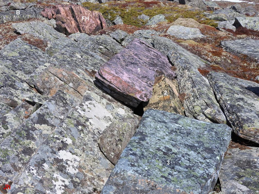
A closeup of the down-slope end of the flow feature (Example 4) is shown above. Blocks have been tinted in this closeup photo to aid in distinguishing them. The block labeled "1" (magenta) and the block labeled "2" (yellow) are two pieces of a single block. Note the right-angled notch in block "1" where it contacts block "2". The upper left-facing surface of block "2" mates with the lower right-facing surface of block "1". The break between the blocks follows an apparent cross joint for less than half the length of block "1", and then follows an irregular fracture line roughly at right angles to the cross joint. Before blocks "1" and "2" were broken apart, the precursor block would have protruded significantly above the surface defined by the top edges of the surrounding blocks. The precursor block was initially a tall frost-heave block that was apparently broken off by horizontally-directed ice loading.
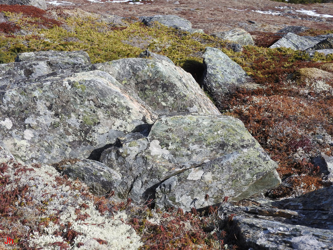
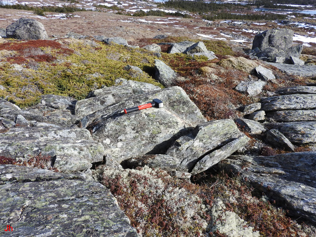
Block "3" (blue) was a frost-heaved joint block that was either broken off from another tall block or ejected from bedrock. Block "3" was moved to its present position by horizontal ice flow. The rock in the background marked "B" is bedrock showing joint widening but lacking obvious frost heave, while the adjacent blocks marked "FH" (red) are frost-heaved blocks. Two views of the blocks marked "FH" are shown below.
Block "3" (blue) was a frost-heaved joint block that was either broken off from another tall block or ejected from bedrock. Block "3" was moved to its present position by horizontal ice flow. The rock in the background marked "B" is bedrock showing joint widening but lacking obvious frost heave, while the adjacent blocks marked "FH" (red) are frost-heaved blocks. Two views of the blocks marked "FH" are shown below.
The small group of frost-heaved blocks shown above provide an indication of what parts of the flow feature (Example 4) might have looked like in the absence of pronounced horizontal loading by glacial ice.
Two wide-angle views of the flow feature (Example 4) and nearby area are shown below.
Two wide-angle views of the flow feature (Example 4) and nearby area are shown below.
The flow feature (Example 4) is seen in the center background of the first photo above and in the center right of the second photo above. Note the smaller rotated bedrock frost-heave feature in the center foreground of both photos. This feature apparently shares a common origin with the main flow feature (Example 4). Both of the above photos help reinforce the theory that the landscape in this area is a hybrid landscape, encompassing aspects of both vertical bedrock frost heave and horizontal bedrock displacement by glacial ice creep.
Example 4 - additional features in local area
The following ice-disrupted bedrock features, mostly lying within a few tens or hundreds of meters of the flow feature (Example 4), are provided to show some of the effects of the pressurized subglacial groundwater that appears to have permeated local bedrock during an episode of cold-based glaciation. It seems reasonable to assume that these ice-disrupted bedrock features were formed contemporaneously with the flow feature (Example 4), during the Younger Dryas cold interval.
Fissures, ice-disrupted bedrock and frost-heaved monoliths
Ice-disrupted bedrock area
Ice-disrupted bedrock with rotated blocks
Ice-disrupted bedrock
Frost-heaved monoliths and ice-disrupted bedrock
Frost-heaved bedrock - Fissure depth = 80 cm
Frost-heaved bedrock - Fissure depth = 1.6 m
Frost-heaved bedrock
Frost-heaved bedrock
Frost-heaved bedrock
All of the features illustrated in the ten photos shown above are found in close proximity to the flow feature (Example 4). Given that the above-pictured features were formed at roughly the same time as was the flow feature (Example 4) then all of the features originated in a cold subglacial environment through the hydraulic action of artesian groundwater working in concert with ice segregation and glacial ice creep.
heartofavalonia.org Exploring Geologic History
