Frost-heaved Bedrock: Illustrative Feature 03
Bedrock disruption beneath thick cold-based glacial ice.
Isthmus of Avalon
Bedrock disruption beneath thick cold-based glacial ice.
Isthmus of Avalon
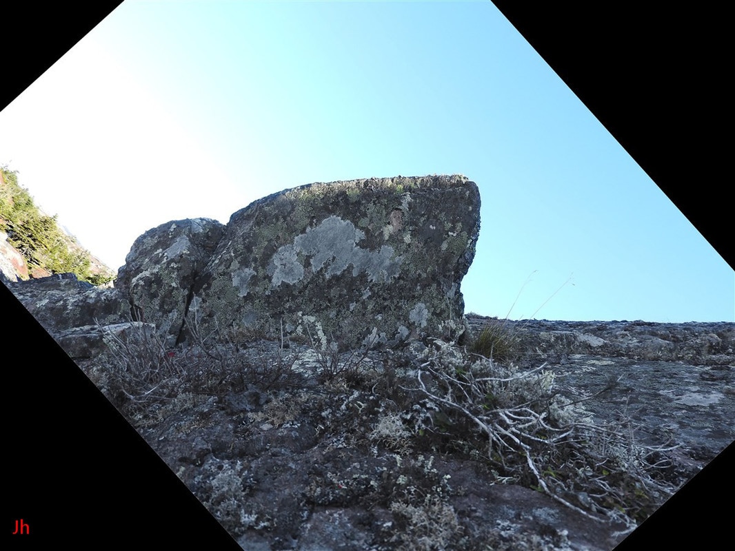
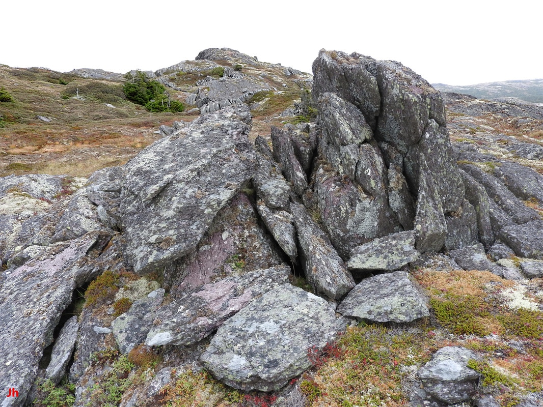
Illustrative Feature IF-03: Is this a roche moutonnee?
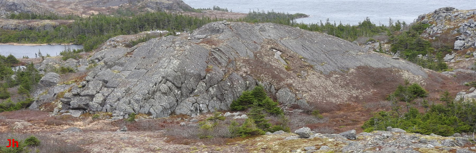
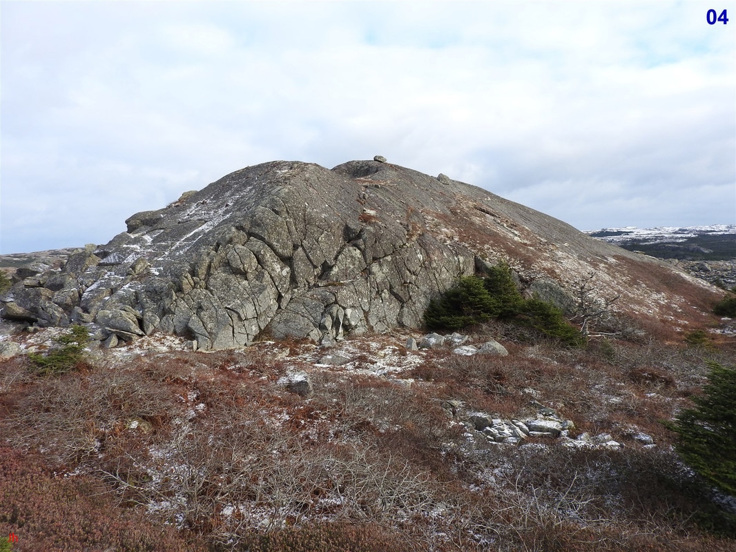
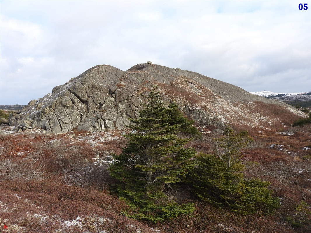
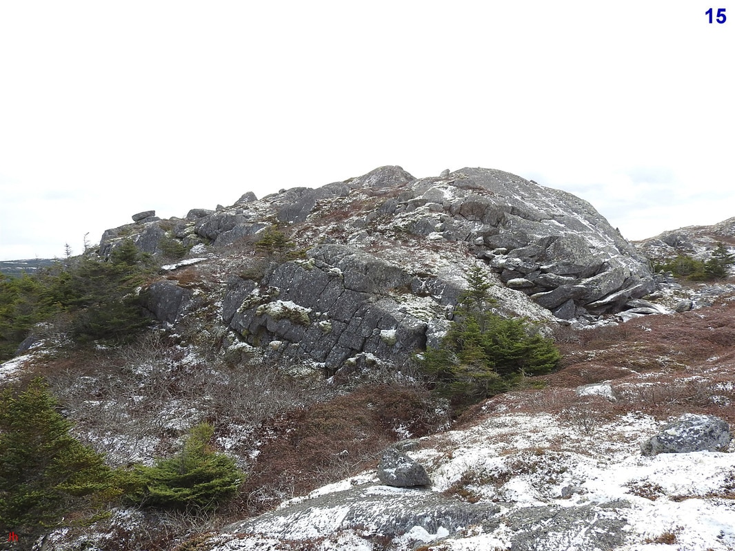
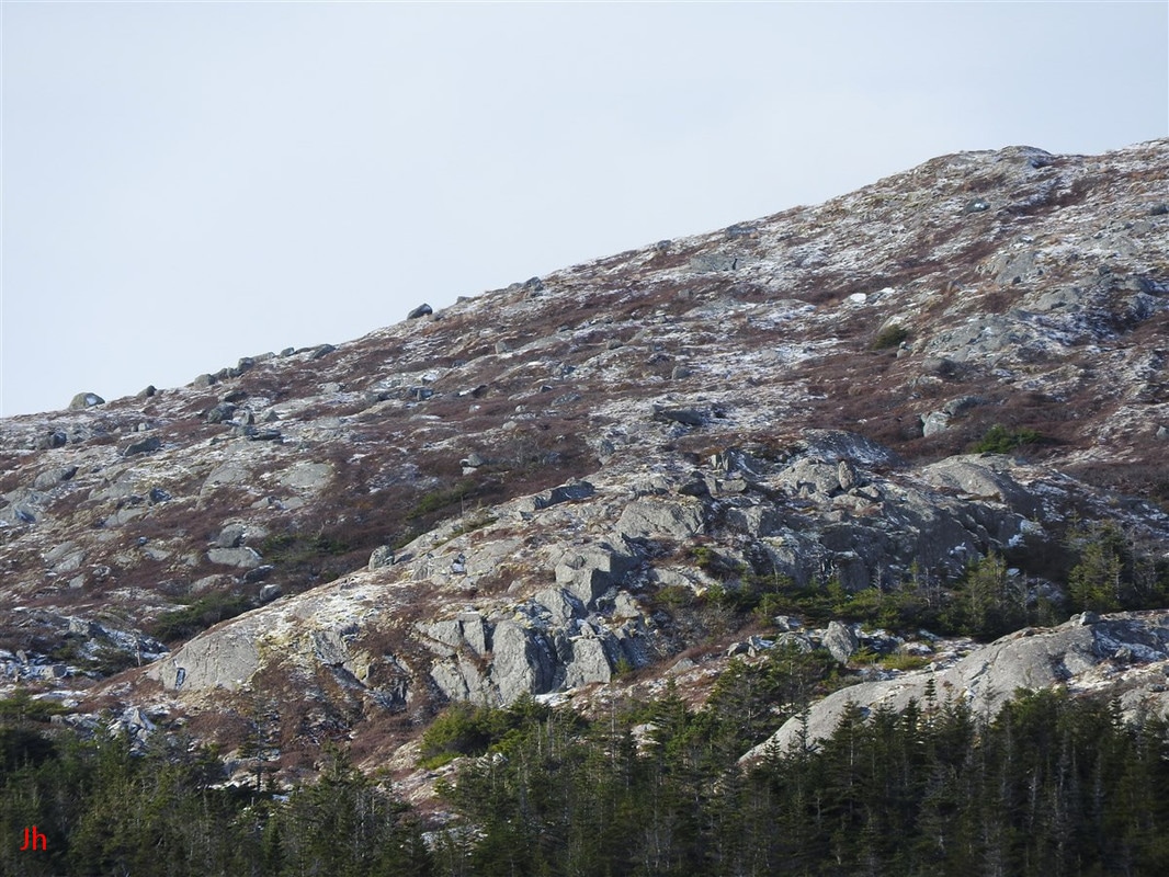
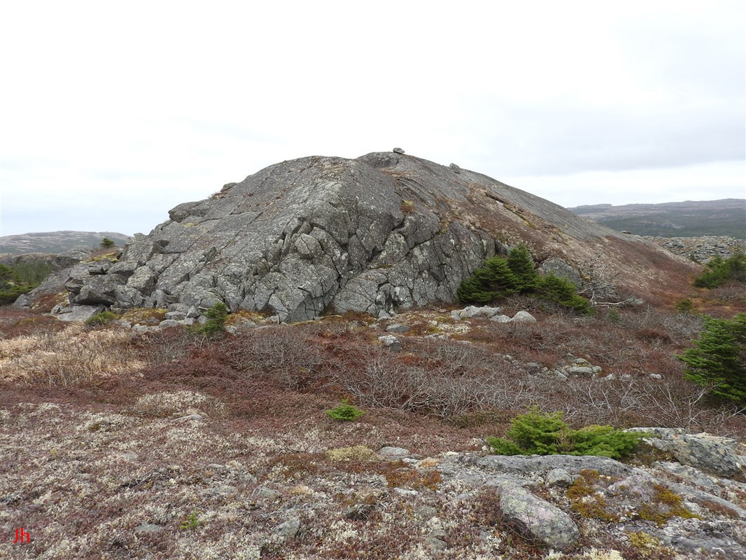
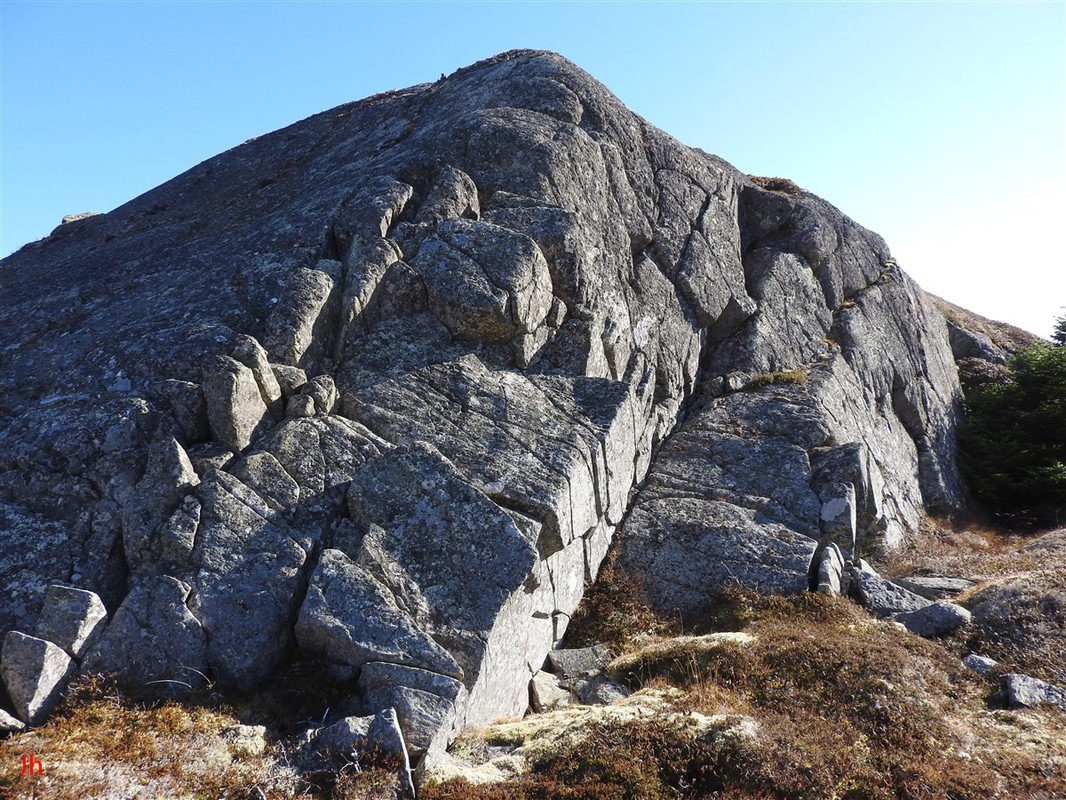
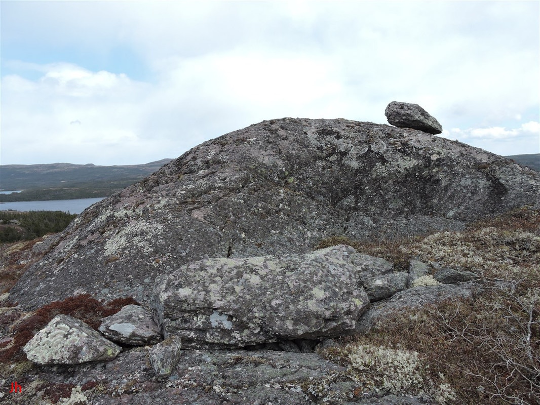
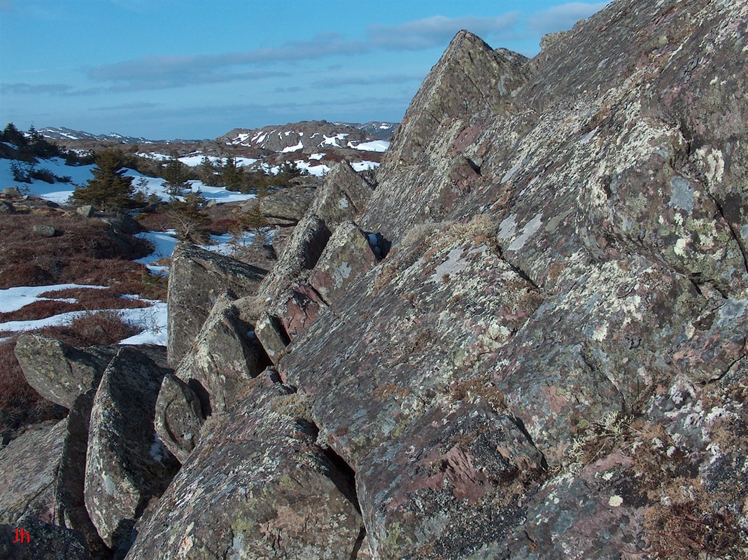
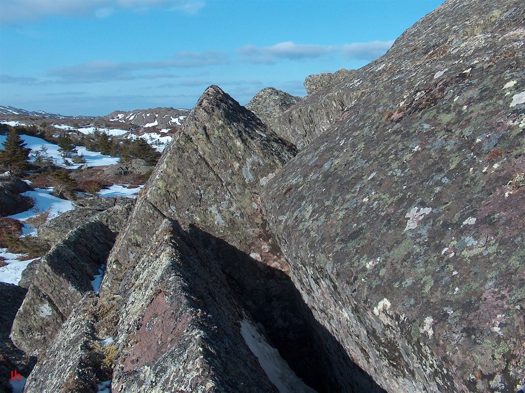
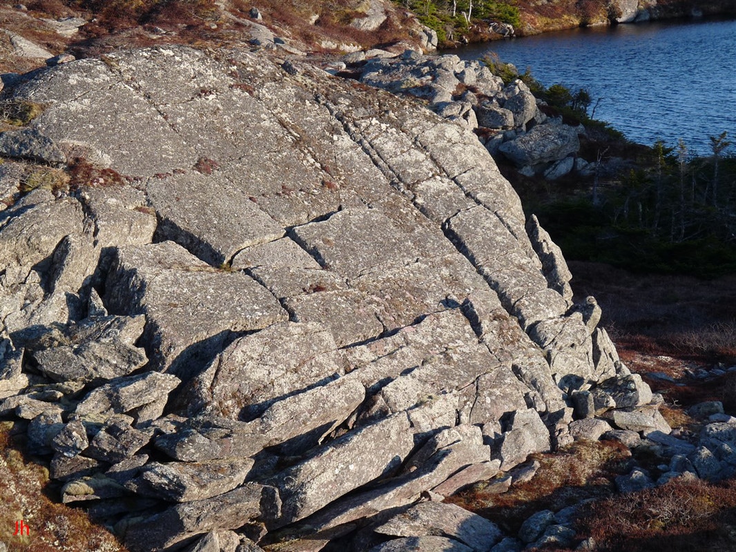
Viewed from the southwest (above photo) the bedrock hill, IF-03, appears in many respects to resemble a roche moutonnee. The streamlining and plucking apparent in the picture leave little doubt that asymmetric erosion by moving glacial ice helped shape this landform. A closer look at the bedrock disruption (above photo, left) suggests that this feature may be indicative of subglacial hydraulic frost-wedging activity. If so, the creep-driven glacial erosion evidenced in this landform could provide a link to other bedrock frost-heave occurrences in the surrounding area. This could help to explain an unusual abundance of large frost-heave features on the Isthmus of Avalon in terms of hydraulic action beneath a cold-based glacier.
Why this hill was picked as an Illustrative Feature:
1) The asymmetry of the feature indicates that moving glacial ice and associated differences in ice pressure were key in shaping the landform.
Bedrock shift on the northwest face of the hill resembles conventional frost wedging in some respects. However, it is unlikely that the disrupted bedrock seen on the northwest face of this hill originated conventionally, that is, during a time of periglacial climate with glacial ice absent.
Instead, the landform appears to provide an example of frost-heave-like processes occurring in a deep subglacial environment.
2) Bedrock disruption, while extensive, has occurred in a restrained manner, leaving bedrock fragments largely in place and subject to positional reconstruction. There is very little rock missing from most surfaces of the initially glacially-smoothed landform.
3) The now-disrupted northwest face of the hill underwent thorough smoothing by basal slip glacial action before large-scale bedrock disruption occurred. This makes the effect of the late-stage bedrock disruption more straightforward to observe and analyze.
4) A well-developed tectonic joint system traversing the entire outcrop has provided sharply defined and aligned failure surfaces combined with deep-seated orthogonal routes for groundwater/ice to penetrate the rock. This makes the outcrop useful for investigating the propagation of ice and ice pressure through bedrock.
5) The approximate 45 degree slope of the pre-disruption plucked face provides a shallow-enough angle that the plucking, in many cases, resembles bedrock frost heave seen on nearby low-sloping or horizontal surfaces. The hill thus provides a bridge between two processes observed frequently in the area: bedrock frost heave and plucking.
6) The hill is in the close proximity of a significant area of abundant large horizontal bedrock frost heave features and analyzing the hill can potentially help in understanding the origin of the nearby features. There are 3 key questions to consider: 1) are nearby horizontal bedrock frost heave features subglacial in origin? 2) If "yes" to the first question, how did pressurized H2O travel through bedrock to cause these features? 3) Given that hydraulic pressure is the cause of subglacial bedrock frost heave, where did the pressure originate?
List of main conclusions regarding the hill, IF-03:
1) The bedrock disruption on one face of IF-03 is glacial in origin. Specifically, the bedrock was shifted by ice creep taking place under glacial ice of probable thickness in excess of 100 m.
2) Hydraulic pressure powered the plucking process, with the most likely source of the pressure arising 10's or 100's of metres distant from the plucked face.
3) The plucking process observed in IF-03 is associated with nearby occurrences of bedrock frost heave seen on horizontal surfaces. It appears likely that the plucked features and the nearby frost-heave features shared a related or common source of hydraulic pressure.
4) The plucked surface on IF-03 was formed beneath a cold-based glacier and rock displacements of the order of 1 m may have taken hundreds of years to develop.
IF-03: Geographic area and overview
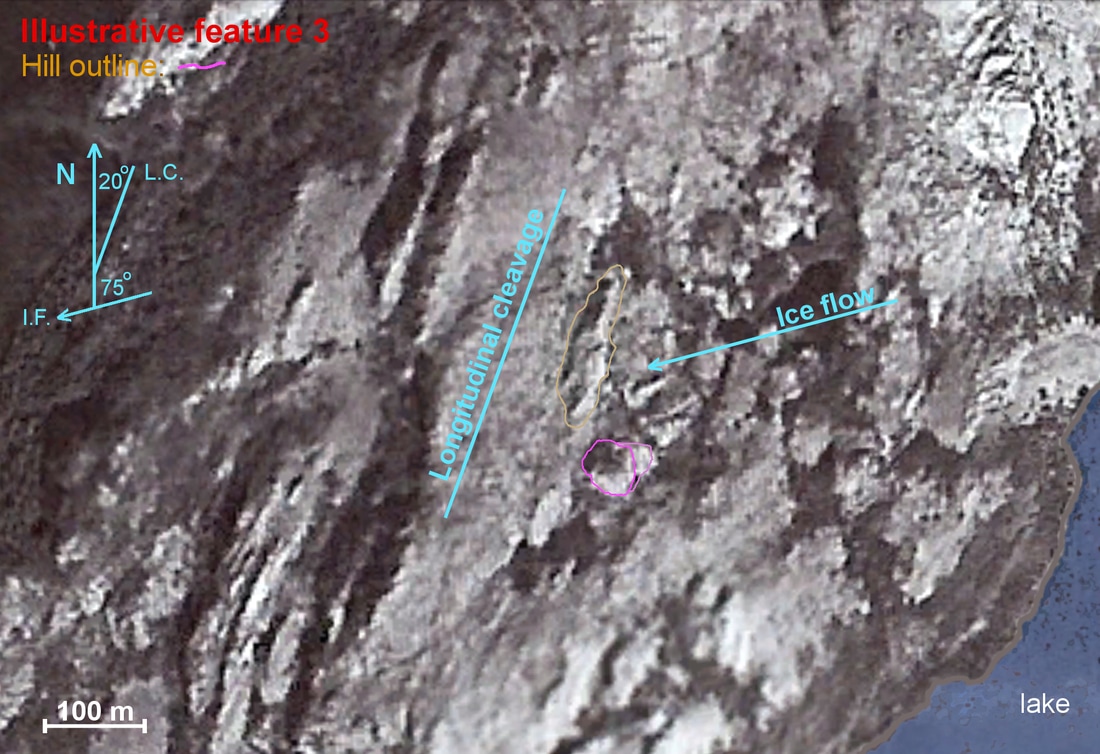
The above high-altitude aerial photograph shows the hill IF-03 outlined in magenta as an irregular circle augmented by a "tail" section extending east-northeast. The circular line represents a steep boundary surrounding the main part of the hill, while the "tail" section is a more gently sloping area of exposed bedrock associated with the main hill but separated from it by a low cliff. The previously described ridge, IF-01, is close to IF-03 and is marked on the airphoto with a dull yellow contour line. The indicated strike for the longitudinal cleavage represents an average for the surrounding area and differs from the strike of the longitudinal cleavage measured specifically for the hill IF-03. The ice flow direction was taken from striations observed on nearby hills since no clearly observable striations were found on IF-03 itself.
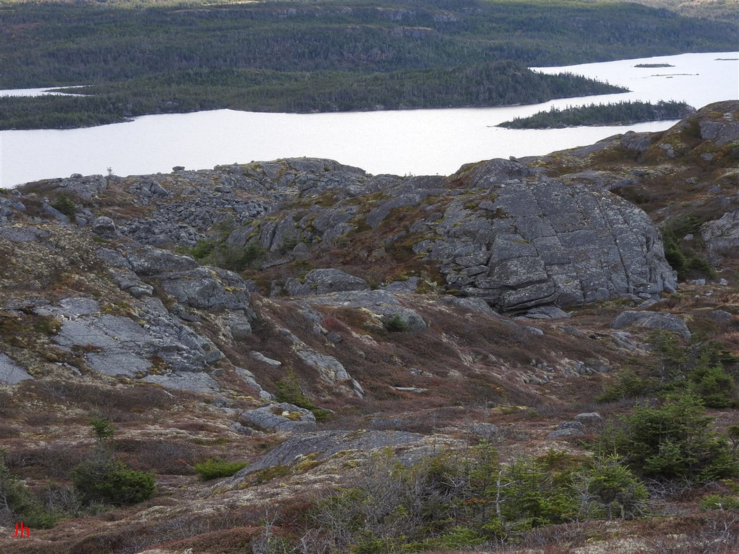
The photo above shows IF-03 viewed from the northwest, looking southeast. The plucked area referenced on the outline diagram below is seen almost face-on at the center right of the photo. The south end of the ridge IF-01 is visible in the foreground of the picture.
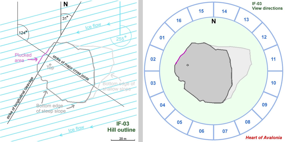
The diagram on the left above shows an outline map of IF-03 providing scale and orientation. Major cross joints intersect the longitudinal jointing at almost 90 degrees. There are two sets of major cross joints as indicated by fissures and failure surfaces visible on the hill. One set of cross joints dips vertically and is displayed prominently on the plucked face of the hill where the joints have been widened into fissures by frost wedging and erosion. A second set of identically-striking cross joints dips at about 45 degrees and forms failure surfaces primarily on the south side of the hill and the southeast corner.
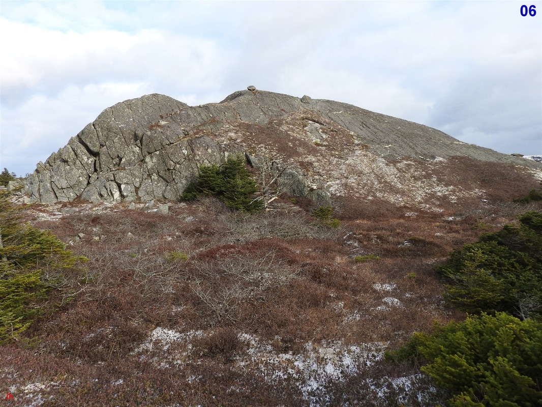
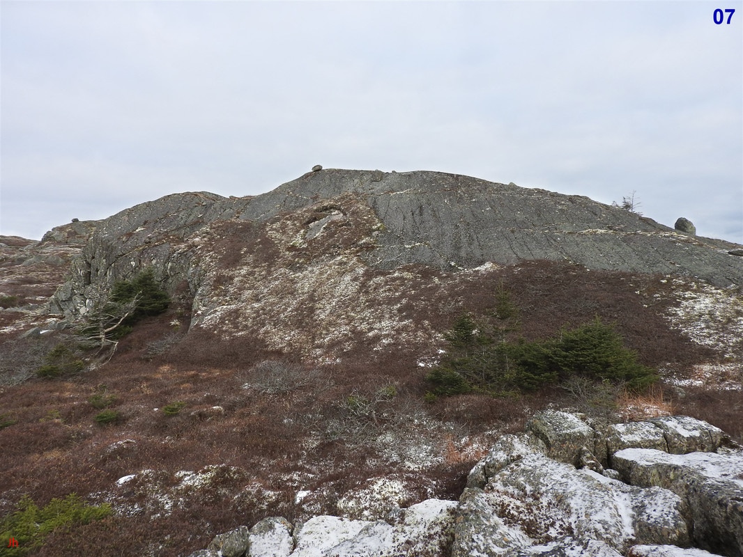
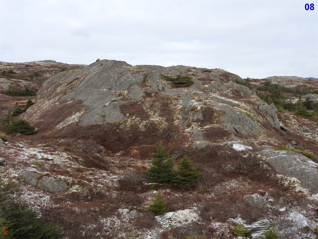
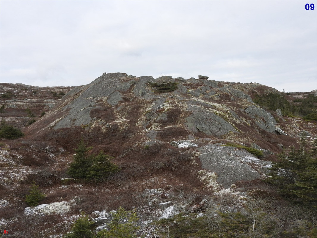
The diagram on the right above provides an index that correlates view angles with compass directions. The video below shows a full 360 degree loop around the hill with photos recorded every 22.5 degrees (1/16 rotation). Numbers placed at the upper right of the photos show the view-direction index. The individual still photos comprising the video are laid out in a grid following the video.
The diagram on the right above provides an index that correlates view angles with compass directions. The video below shows a full 360 degree loop around the hill with photos recorded every 22.5 degrees (1/16 rotation). Numbers placed at the upper right of the photos show the view-direction index. The individual still photos comprising the video are laid out in a grid following the video.


Ice path
Glacial ice flowed over the the top of the hill IF-03 in the direction indicated on the preceding outline diagram. The indicated direction (255 deg. true) is a late-stage ice flow direction and it is likely that ice flowed over the hill in other directions during the main portion of the Wisconsin glaciation and during previous Pleistocene glacial episodes. Evidence in the region of IF-03 suggests that, during deglaciation, ice flow direction did not change appreciably, even as the thermal regime of the overlying glacier transitioned from temperate to polythermal to cold-based. End-stage ice flow direction at the location on the Isthmus of Avalon that includes IF-03 was almost exactly orthogonal to the western coastline of the Isthmus and was directed toward Placentia Bay.
Ice moving toward IF-03 would originate in, or cross over, a long wide valley lying close to the east-to-west center of the Isthmus. The valley is tectonically aligned and follows a probable syncline. The present-day elevation of the valley floor (occupied by a string of lakes) is about 65 m (lake surface) above present-day sea level. It is likely that the center of this valley lay underneath the thickest portion of the ice cap remaining on the Isthmus of Avalon just prior to deglaciation. The center of the valley (camera position in photo below) lies about 1.1 km up-ice from the center of the hill IF-03.
Ice moving toward IF-03 would originate in, or cross over, a long wide valley lying close to the east-to-west center of the Isthmus. The valley is tectonically aligned and follows a probable syncline. The present-day elevation of the valley floor (occupied by a string of lakes) is about 65 m (lake surface) above present-day sea level. It is likely that the center of this valley lay underneath the thickest portion of the ice cap remaining on the Isthmus of Avalon just prior to deglaciation. The center of the valley (camera position in photo below) lies about 1.1 km up-ice from the center of the hill IF-03.
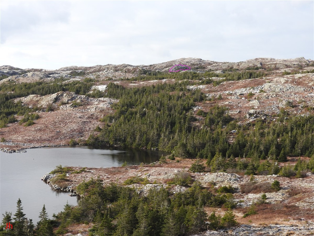
The hill, IF-03, is shown in the above photo, outlined in magenta. The view toward IF-03 is aligned directly along the route followed by glacial ice as it moved from the center of a long valley (camera position) toward IF-03 and then, to the coast. To clear the ridge forming the background of the above photo, ice starting at lake level (65 m above sea level) would need to gain about 100 m additional height before descending along a 4 km long stretch of rugged terrain to reach the sea.
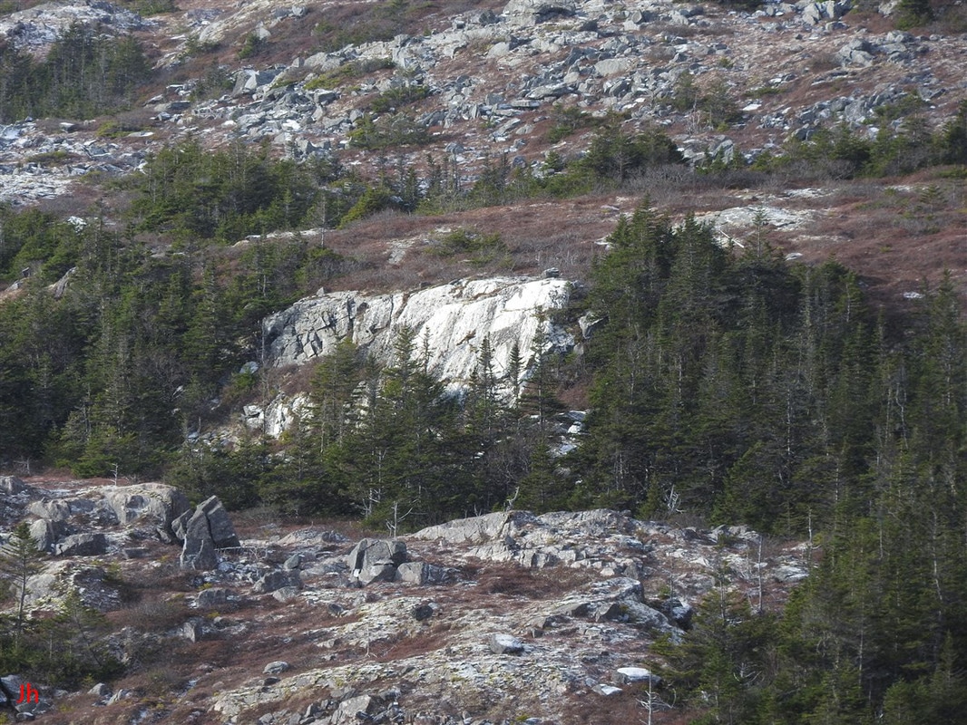
Note carefully the white cliff appearing below and to the right of IF-03. This cliff is formed by a large quartz vein that was exposed by glacial erosion. The face of the cliff bears long, vertical striations and chatter marks caused by pebbles from up-ice ignimbrite being dragged straight up the cliff by ice flow. Proof that the ice flow was ascending the cliff (rather than descending) was provided by bedrock fragments that had been lifted by ice flow and then jammed such that they held their elevated position after the ice departed. A closer view of the quartz cliff is shown below. A more detailed description of this cliff will be provided in another section (pending).
Note carefully the white cliff appearing below and to the right of IF-03. This cliff is formed by a large quartz vein that was exposed by glacial erosion. The face of the cliff bears long, vertical striations and chatter marks caused by pebbles from up-ice ignimbrite being dragged straight up the cliff by ice flow. Proof that the ice flow was ascending the cliff (rather than descending) was provided by bedrock fragments that had been lifted by ice flow and then jammed such that they held their elevated position after the ice departed. A closer view of the quartz cliff is shown below. A more detailed description of this cliff will be provided in another section (pending).
|
|
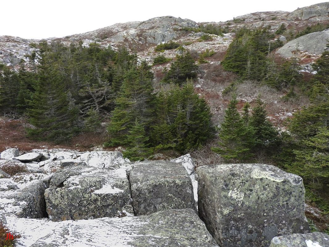
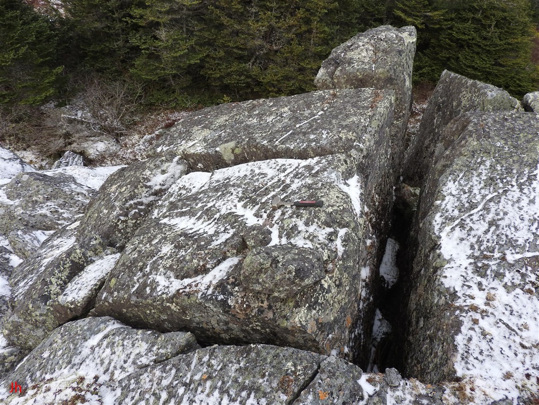
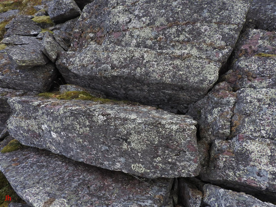
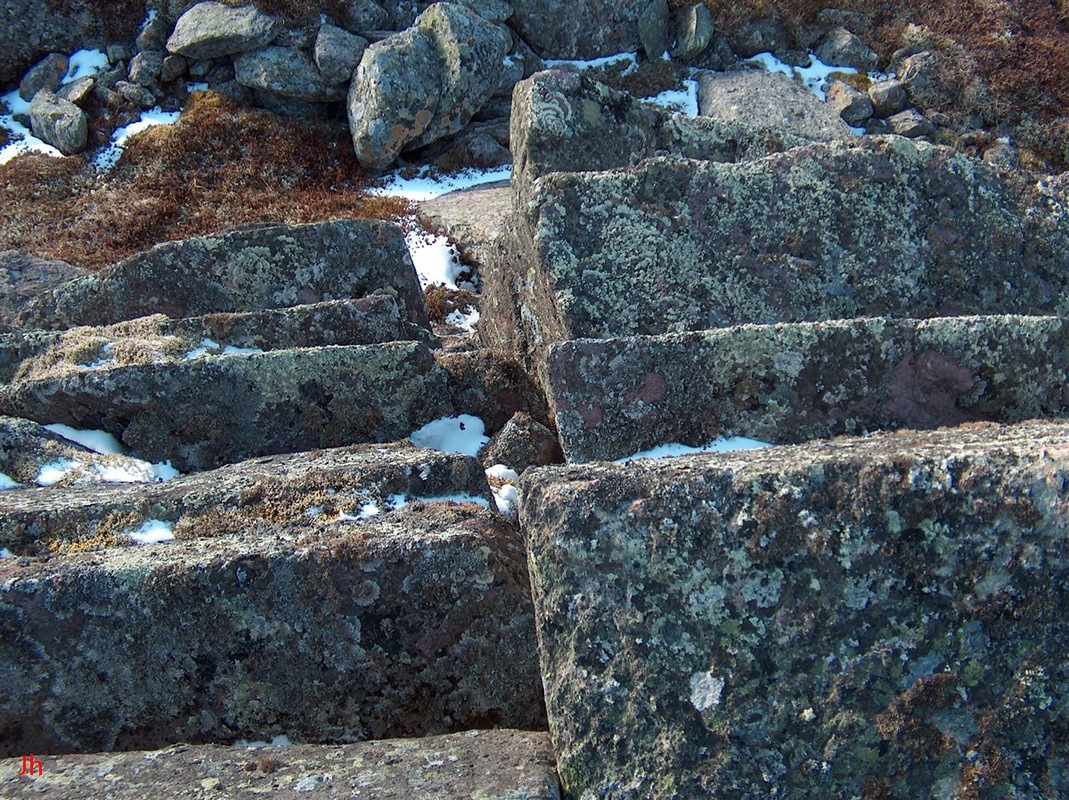
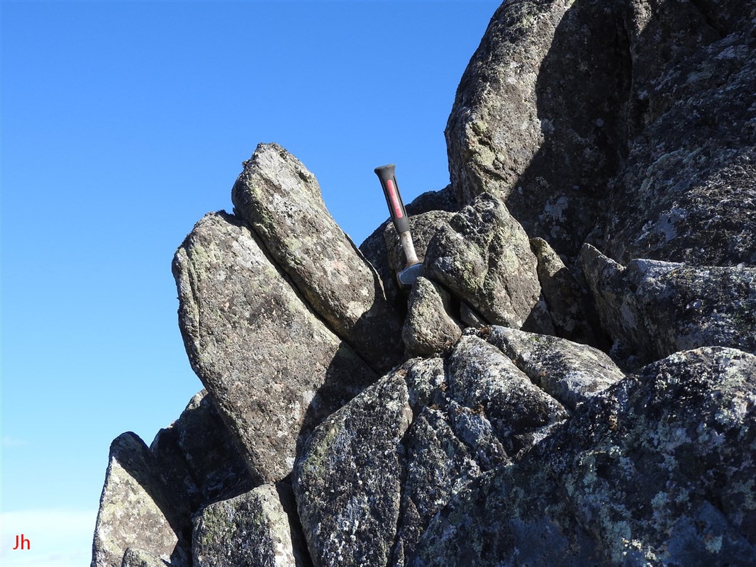
The hill (IF-03) can be seen in the top center of the frame, along the horizon, in the first (left) photo above. The view direction is aligned with the ice flow direction (pointing down-ice). Large joint blocks appearing in the foreground have been displaced by ice pressure, opening the fissure shown in the second (right) photo. The hammer in the right photo (27 cm long, center, hard to see) shows scale. Relatively small displacements of large blocks such as are shown above, indicate limited creep-driven ice motion and suggest that the rocks were shifted beneath a cold-based glacier.
|
|
|
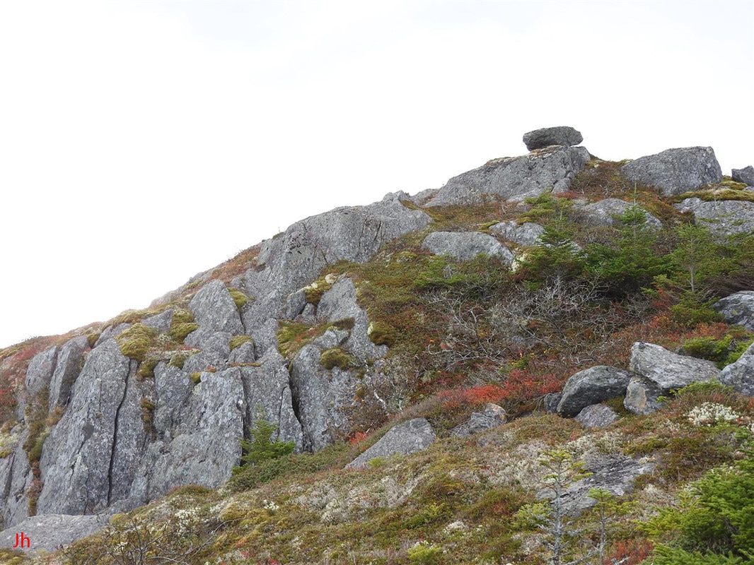
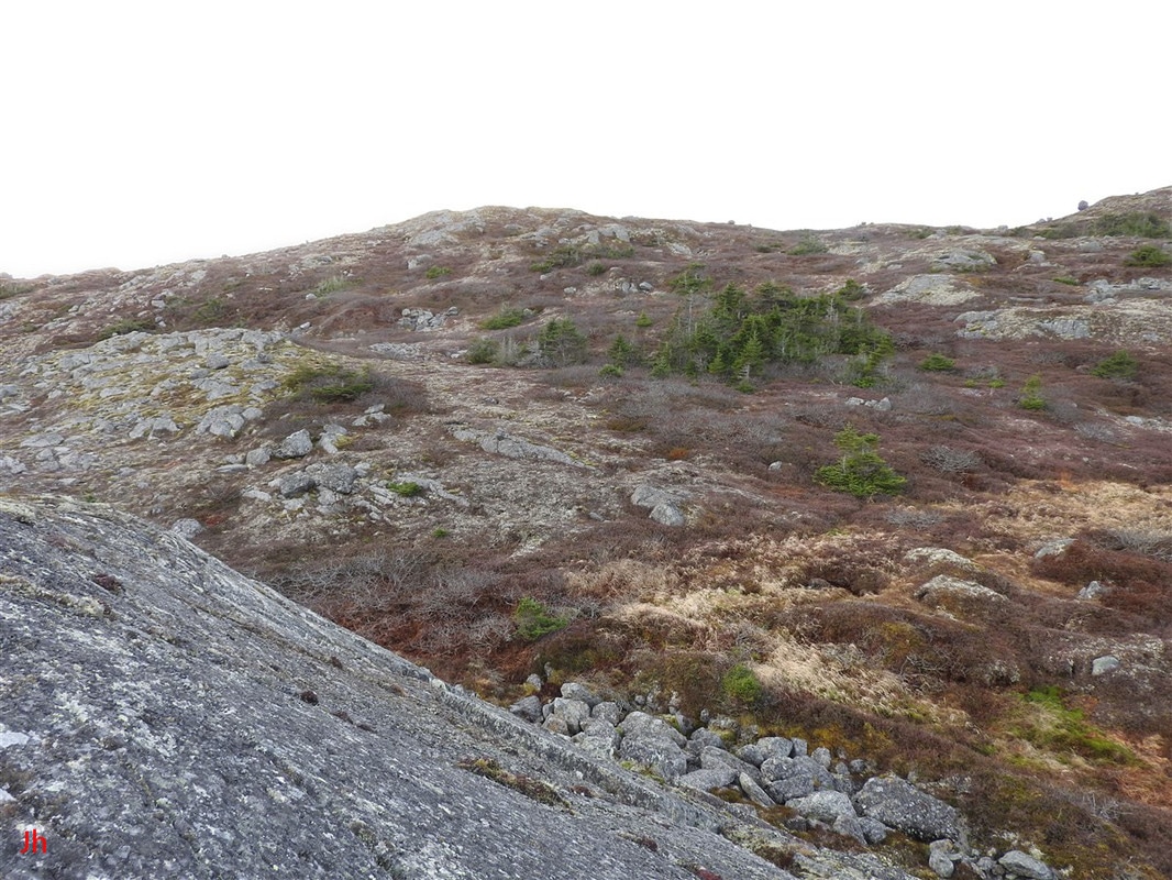
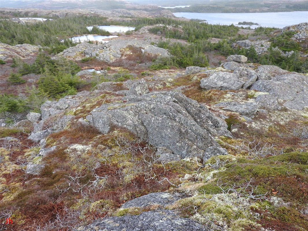
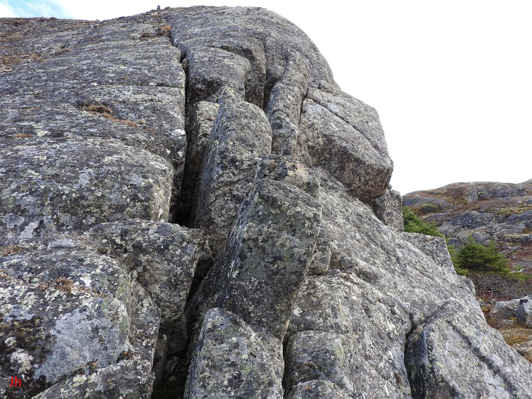
|
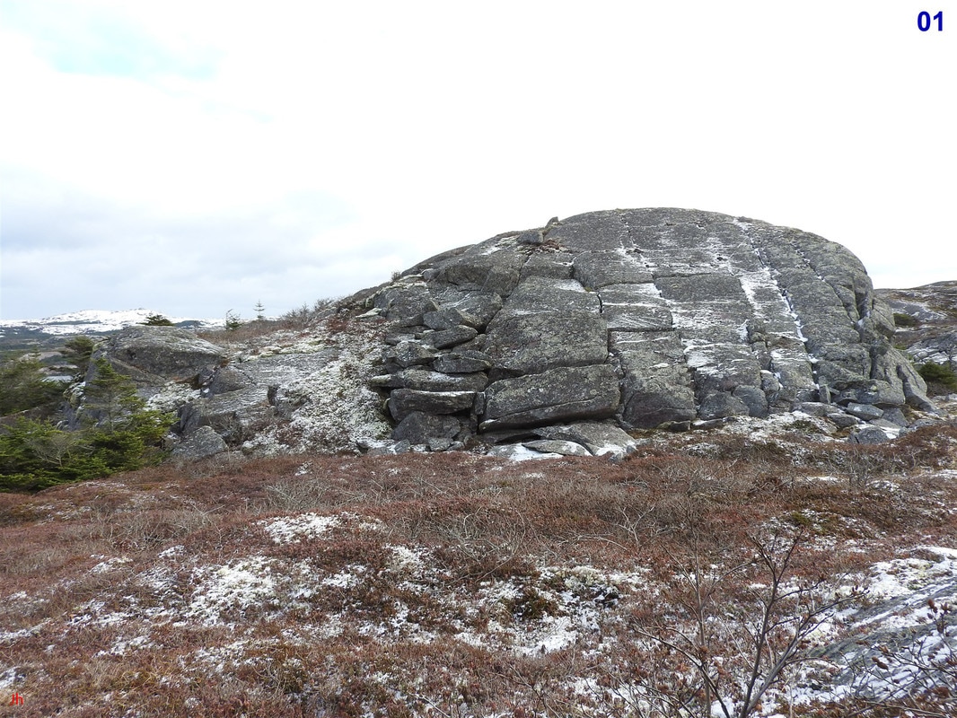
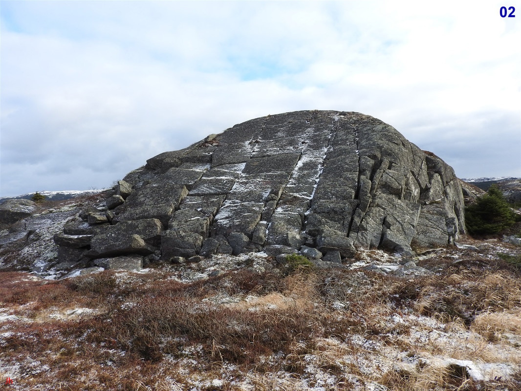
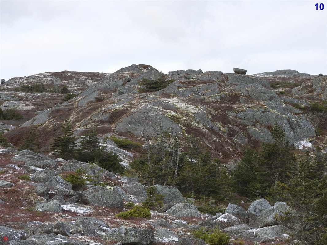
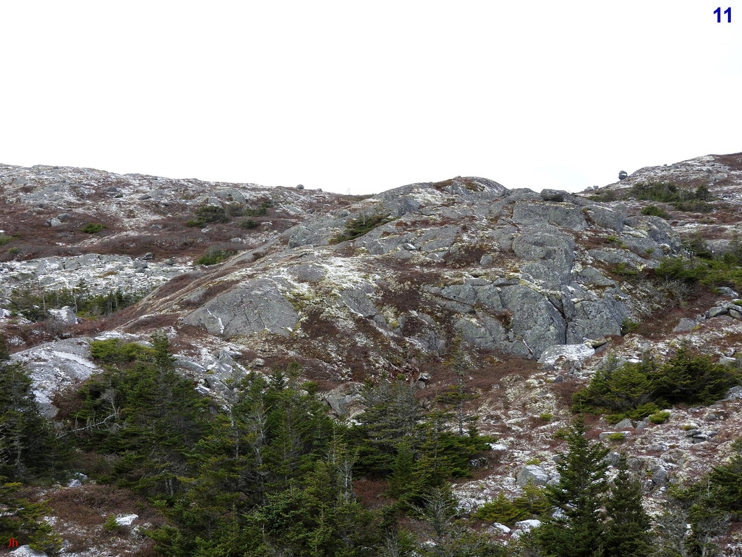
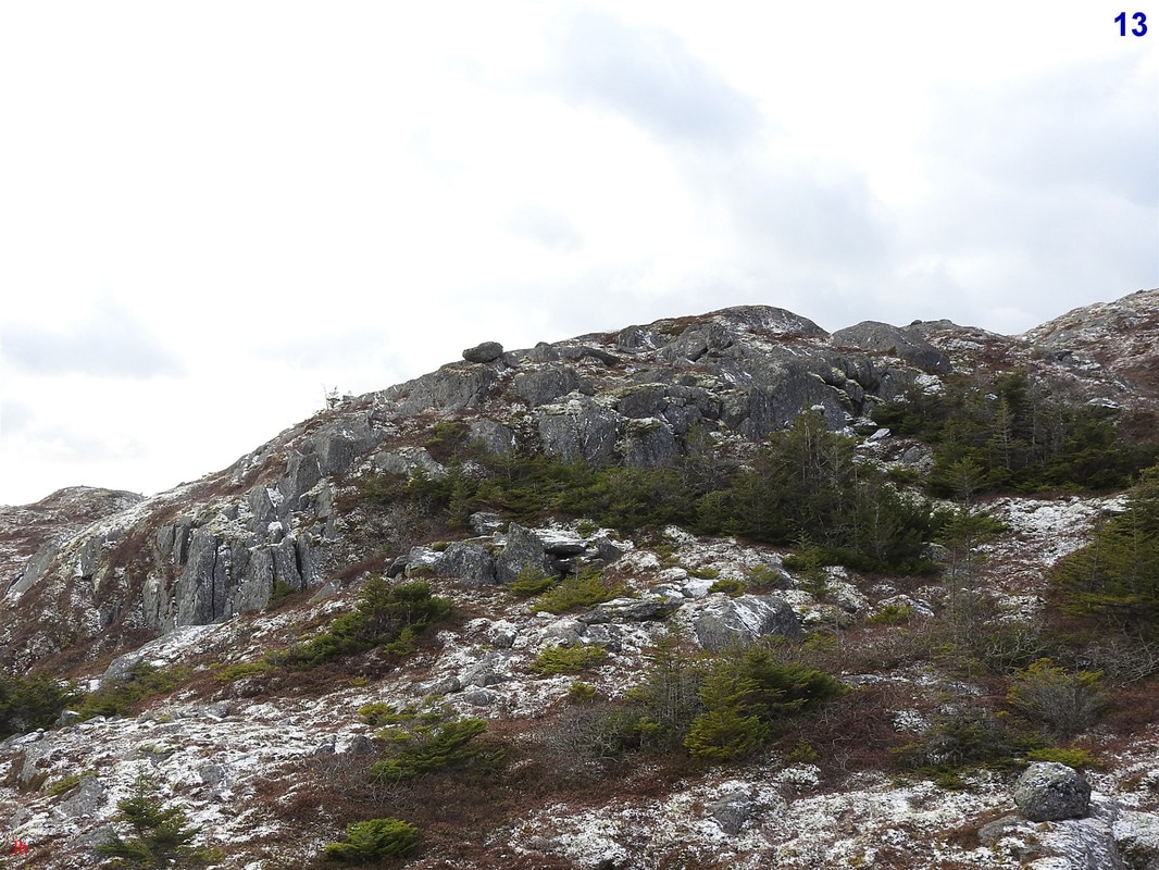
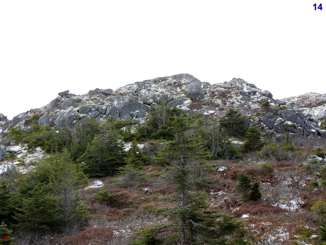
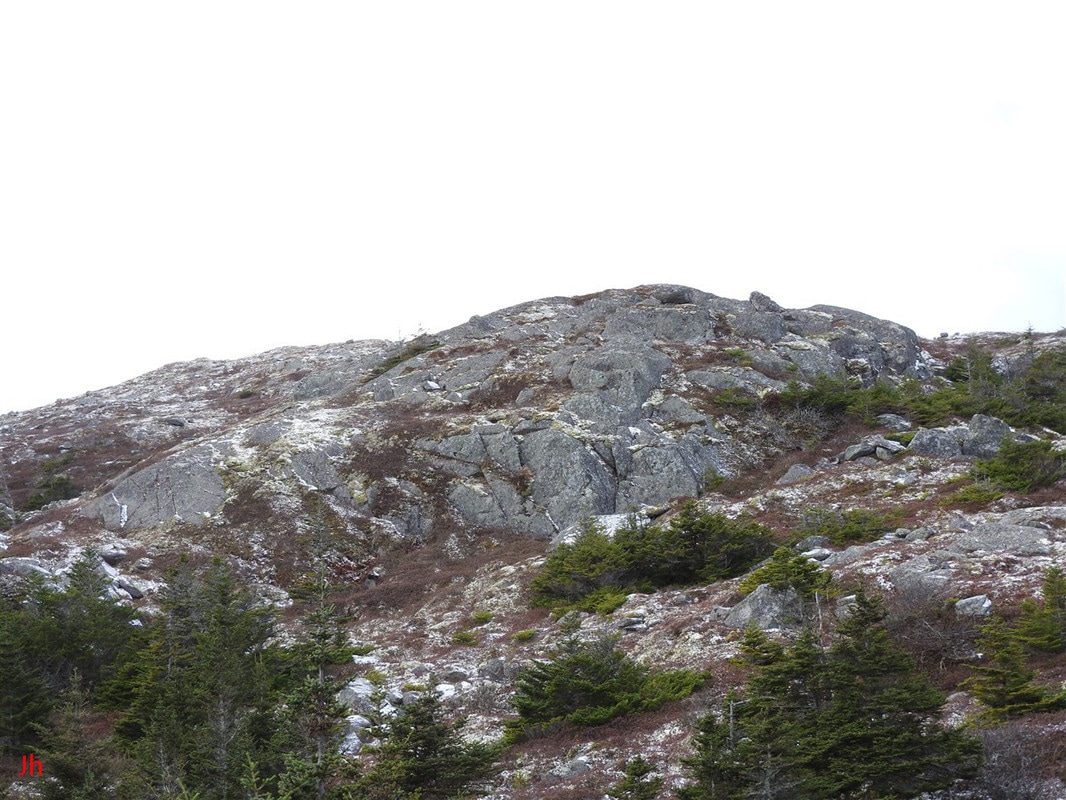
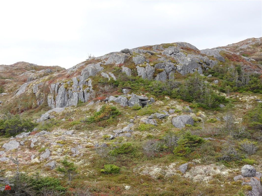
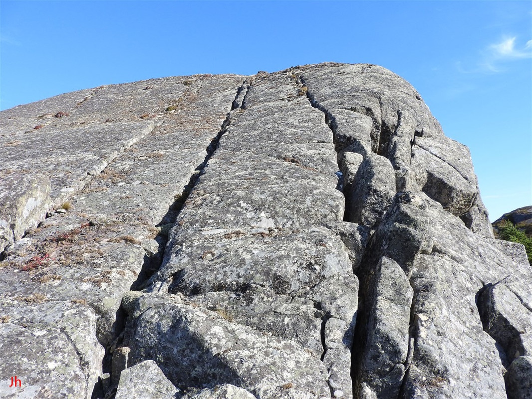
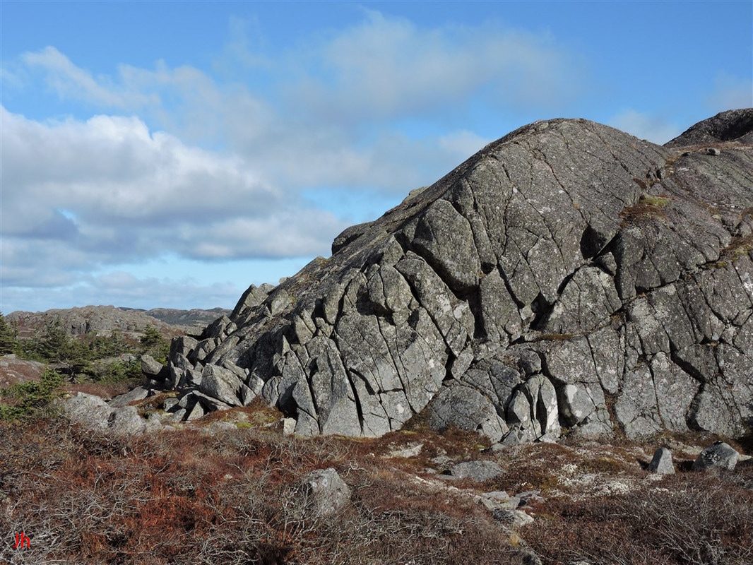
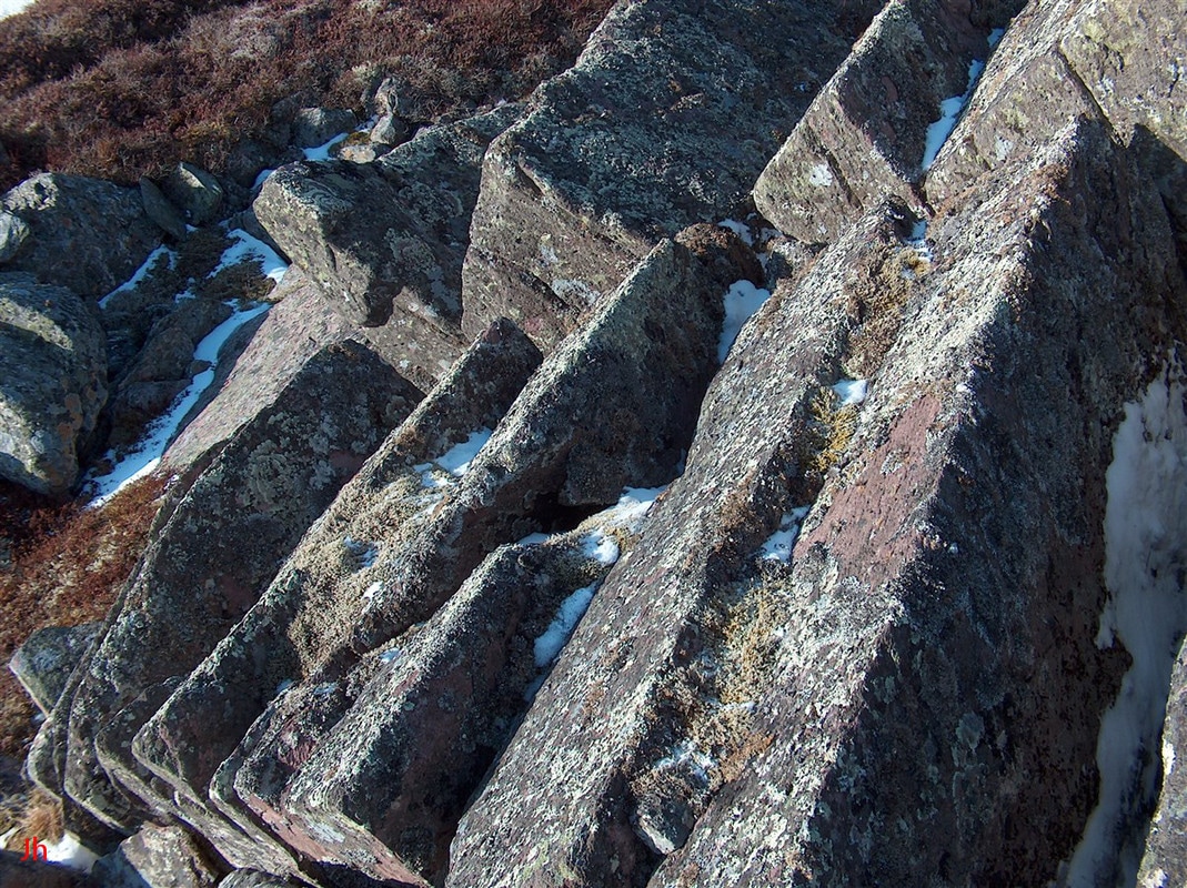
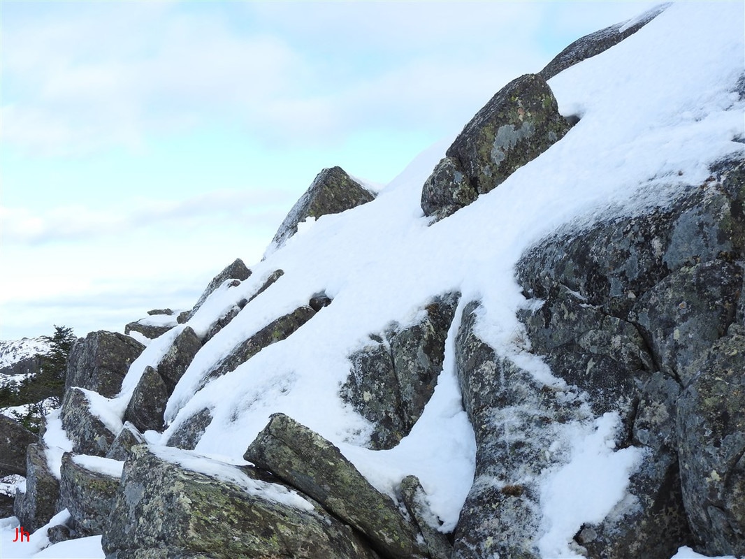
Four views of the approach to IF-03 along the ice flow path (looking down-ice) are shown above. The rock is not as streamlined as would be expected on the up-ice side of a roche moutonnee. The flattened rock faces are failure surfaces along the pronounced longitudinal cleavage characterizing this hill. Note that some longitudinal joints have been widened into fissures. This widening could reflect rebound from ice loading (exfoliation) or it could have been caused by ice/groundwater pressure within the bedrock body of the hill exceeding the external ice loading pressure. Other nearby instances of bedrock displaced resolutely against ice flow direction suggest that the second explanation is more likely.
|
|
Both of the above pictures were taken from the top of the hill, IF-03. The first (left) photo shows the outgoing ice path leading west-southwest, toward the ocean, while the second (right) photo shows the incoming ice path extending east-northeast from the center of the isthmus. The bedrock outcrop at the centre of the second (right) photo is noteworthy. This section of rock contains several deep fissures (not well aligned for visibility) and shows evidence of ice having moved upward through the fissures. This feature will be discussed in more detail under the heading "Related external features" further along in this IF-03 description.
The view shown above is directed along the path taken by ice moving over the hill and straight toward the camera. The rock face pointing directly at the camera (lee-side face) shows evidence of plucking and subsequent complete removal of the resulting fragments. This plucking may have occurred during a phase of warm-based glaciation where large-scale ice motion carried the broken rock far down-ice. It is clear from the above photo that plucking on the adjacent northwest face of the hill (left side on photo) was not closely aligned with the ice flow direction (see also the outline diagram presented above in this section). Rather, the rock failure seen on the northwest face was guided by planes of weakness following the longitudinal cleavage in the bedrock. It is reasonable to conjecture that the plucking visible in the above photo occurred in two stages, a warm-based basal-slip stage (center of photo, lee-side) followed by a cold-based creep stage (left of photo). Within this hypothesis, the hill is a roche moutonnee, but only the plucking seen in the center of the photo conforms with the most common characterization of this type of landform.
A closeup of the lee-side (center, previous photo) plucked face of IF-03 is shown above. Rock has been transported away from the prominent failure surface shown in the center foreground, probably by basal-slip ice movement. This failure surface follows the major set of vertically-dipping cross joints running through the rock at approximate right angles to the longitudinal cleavage.
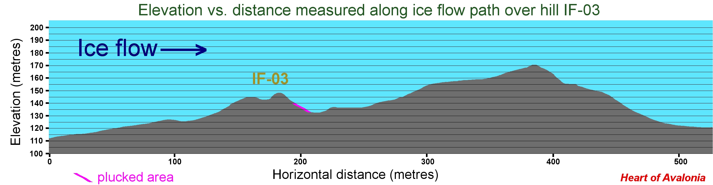
The above chart shows the elevation profile for IF-03 and the surrounding topography, measured along the ice path running directly over the top of the hill, IF-03. The center of the Isthmus of Avalon lies to the left of the chart and the Placentia Bay coast lies to the right. There is little evidence of ice diverting around the landforms in its path and it appears that, during deglaciation, ice was flowing along the shortest route from the isthmus center to the ocean shoreline. This would imply that the ice thickness along the spine of the isthmus substantially exceeded the variations in topographic elevation along the route to the coast and that the gradient in ice elevation was sufficient to drive ice seaward over all obstacles. The "plucked area" marked on the chart is not the lee-side plucked face described above but rather is the adjacent northwest-facing area (area shown on the photo immediately below and marked on the outline diagram for IF-03 presented previously in this section).
Observations of the plucked area
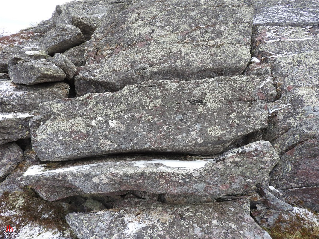
The primary area of interest (plucked area) is shown in the above photo. The vertical height of the pictured sloping front face is about 13 m. The horizontal width of the face at ground level is approximately 16 m. An oblique view of the same area is shown below.
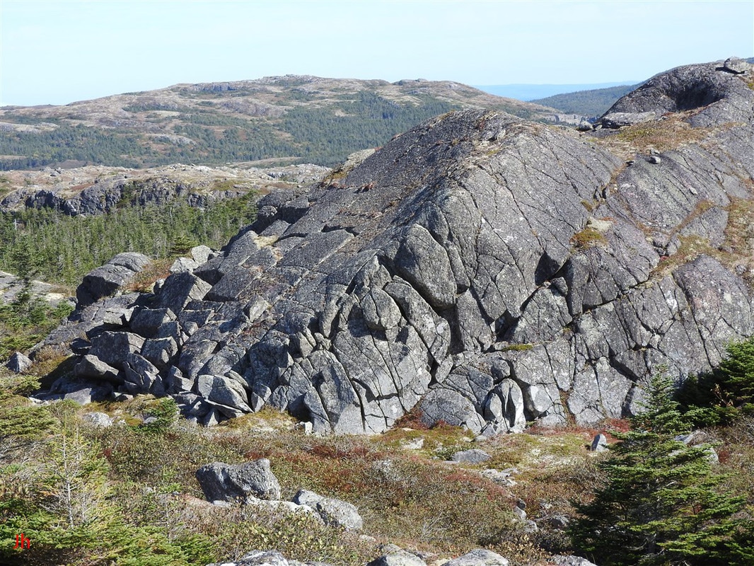
A hill face defined by bedrock that had been smoothed by basal-slip ice flow has apparently been wedged apart along longitudinal joints and then individual joint blocks were lifted and tilted by ice action. The intensity of bedrock disruption increases with decreasing elevation, with the rock at the top of the hill being unshifted, while the rock at the base shows maximum disturbance.
|
Top of hill
|
Bottom of hill
|
|
|
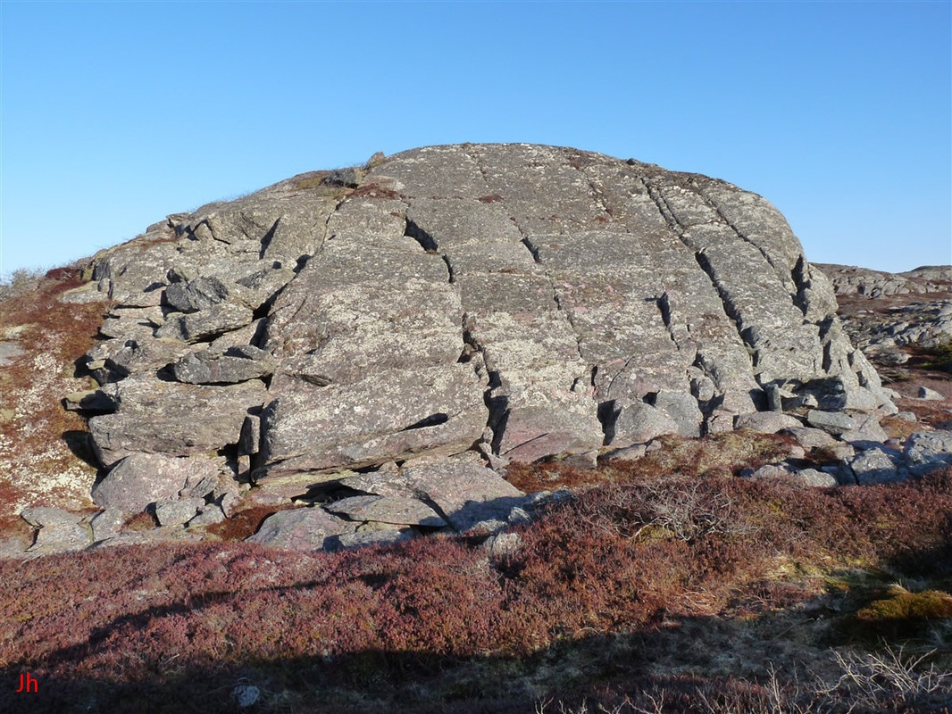
The loose rocks seen in the first (left) photo above are erratics deposited on an an unbroken bedrock surface that has been smoothed and rounded by basal-slip erosion. The joint blocks seen in the second (right) photo above were pushed upward and outward from the bottom of the rock face by ice pressure.
The photo above shows two of the major cross joints traversing the hill as they intersect the plucked rock face. These joints have been widened into fissures by glacial-period ice pressure and/or erosion by rainwater during the post-glacial period.
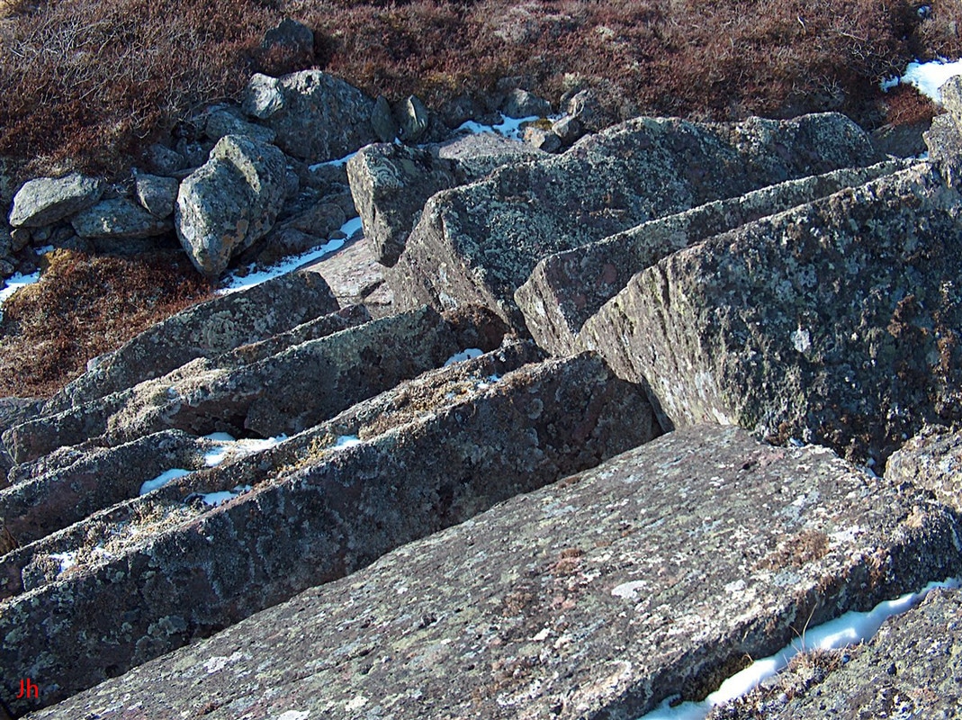
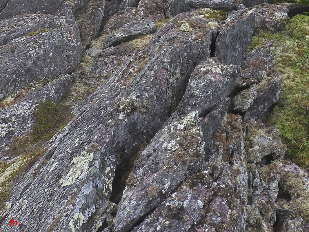
The above side-on view, taken from the southwest, looking northeast, shows longitudinal jointing near the top of the hill giving way to fissures and disrupted bedrock near the bottom. Notice how some large joint blocks have been shifted to protrude above the plane of the hill face which slopes at 45 degrees.
|
|
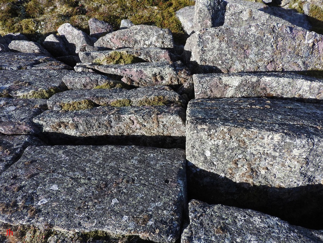
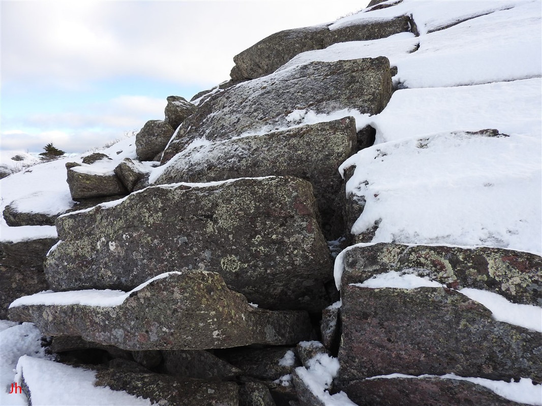
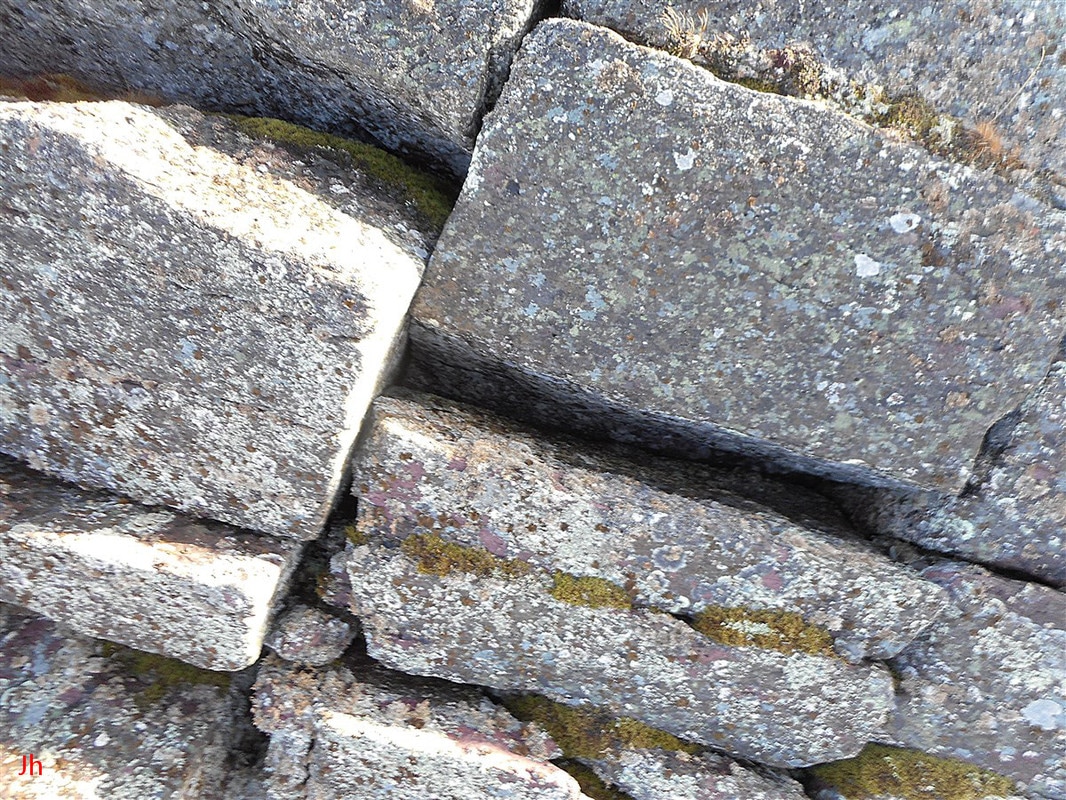
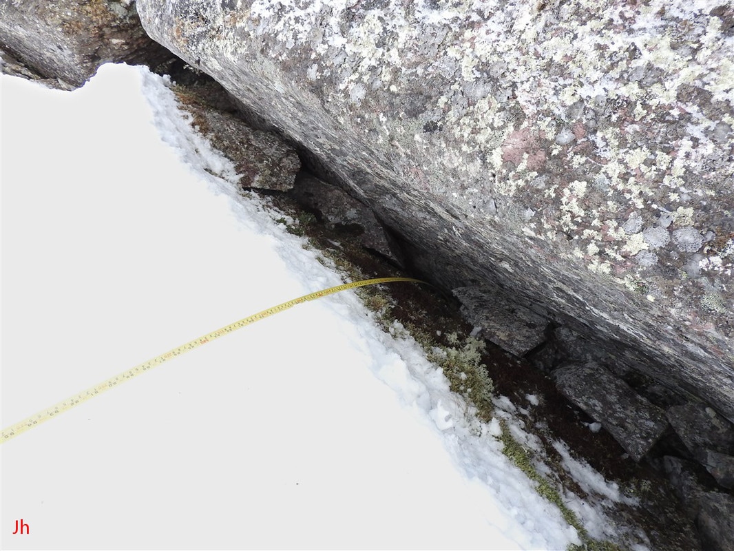
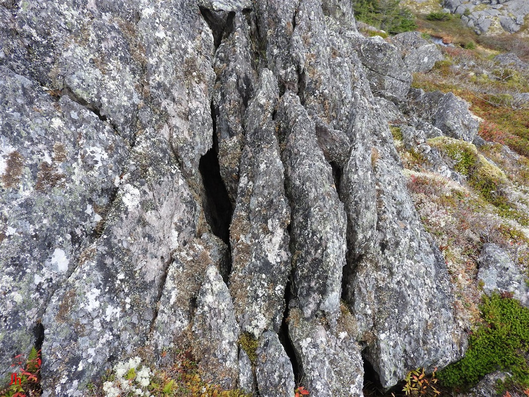
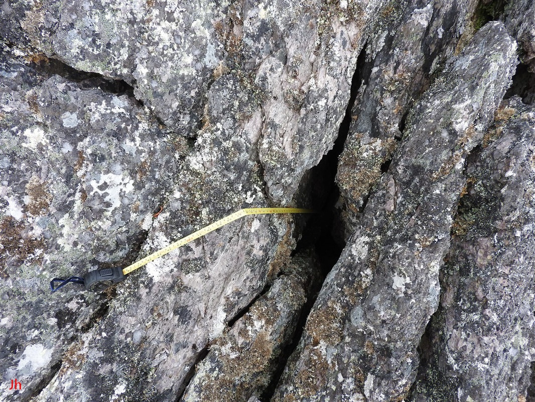
The eight pictures shown above illustrate the staircase pattern of shifted bedrock in the lower central portion of the northwest hillside (plucked area). For scale, note the bottom left photo (seventh in the sequence) showing a column of five joint blocks (left of photo) with lesser snow cover. The heights of the front faces of the bottom four blocks (starting from the bottom) are: 27 cm, 80 cm, 55 cm and 130 cm. The width of the column is about 3.5 metres. The individual blocks are separated by deep fissures, as shown below.
|
|
The depth of the fissure shown in the second (left) photo above is 2.8 metres. At this depth, the bottom of the measuring tape reached debris and it was not possible to determine if the individual joint blocks extended deeper than this.
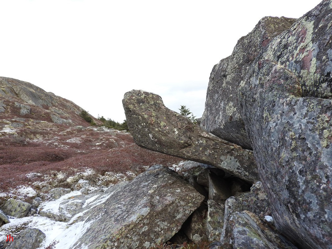
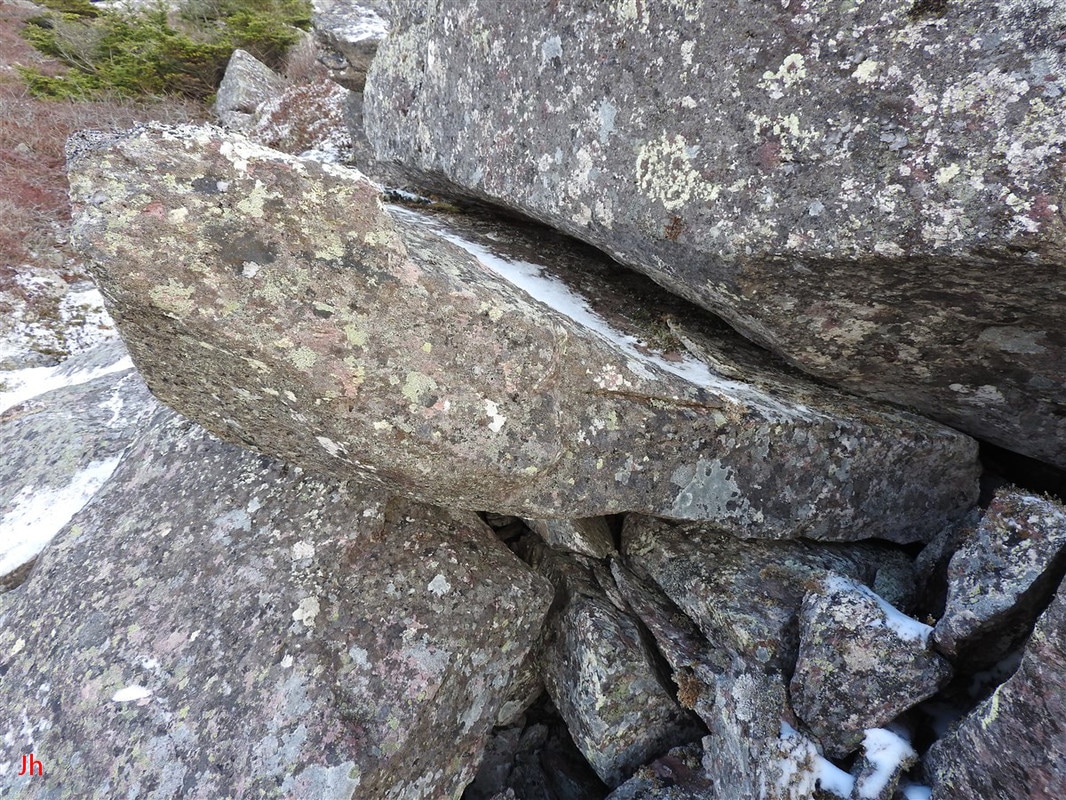
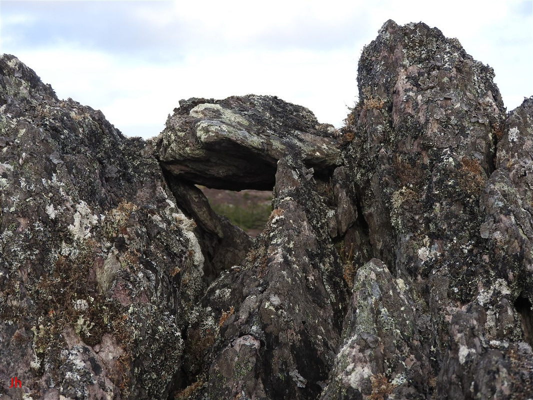
The above photo shows the bottom of the hill near the north edge of the plucked area. The slab of rock seen at the center of the photo has been shifted leftward by ice pressure from within the hill. A section of rock immediately below the shifted slab has been pushed completely clear of the rock face and is now tipped downward. The extended overhanging slab reaches 1.2 m out from the estimated original plane of the rock face.
|
|
Two more views of the same shifted joint block are given above. The first (left) photo reveals the back end of the block. The block was 2.0 m long, front-to back. The second (right) photo above shows the width of the slab (slab is just below the block in the center). The slab measured 3.5 m wide. The space behind the slab contained broken rock debris.
The slab shown above was considered significant for three reasons:
1) Its observed shift demonstrates ice flow emanating from the joint system within the hill.
2) Its precarious cantilevered position suggests that basal slip ice motion did not occur down the face of this hill after the slab was shifted.
3) The slab closely resembles an occurrence of bedrock frost heave, albeit at a low angle of dip.
The above overhead view of the plucked area, taken from the north-northwest, shows a column of disintegrated rock on the left. There is little evidence of rock having been removed from this column. Rather, joint blocks seem to have failed and ice then entered the intervening space leaving remnants of what resembles a small rock glacier. The joint block at the bottom of the smashed column has been tipped outward but is otherwise not significantly displaced. The adjacent column, which is more intact, shows what appears to be a sunken block (center left of photo) part way up. Unless rock was pushed out from underneath this block (an unlikely occurrence), the surface of sunken block would represent the original plane of the hill face. Thus, the nearby blocks are evidently lifted up and are indicative of widespread frost heave and development of an ice lens beneath the lifted rock. Measurement of the depth of a fissure near the sunken block indicated that such an ice lens lay at least 2.2 m below the surface.
Analysis of the plucked area
The above diagram shows a "best guess" illustration of the underground profile of one of the disrupted bedrock columns in the plucked area. The complete expulsion of one or more joint blocks at the bottom of the column leaves room for the upper blocks in the column to tilt forward. The same ice pressure that shifted the main joint blocks also broke up some of the subsurface rock leaving debris and empty space beneath the lifted and tilted joint blocks. A similar pattern has been observed beneath frost-heaved joint blocks seen in the neighborhood of IF-03 on non-sloping (horizontal) bedrock surfaces.
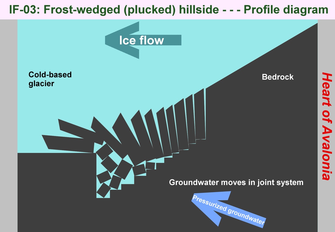
The indicated ice flow direction (green arrow) points only to the general trend observed for the surrounding region and does not account for descending ice as must occur in the lee of the hill, and for the oblique component of ice motion (component out of the plane of the diagram, toward the viewer). It has been assumed that groundwater (blue arrow) moving within the joint system present in the bedrock drove the frost-wedging process and provided the ice volume needed to fill space beneath the displaced rock. The key (albeit as yet unclear) concept in understanding the bedrock disruption process is to understand how this groundwater originated and moved.
The indicated ice flow direction (green arrow) points only to the general trend observed for the surrounding region and does not account for descending ice as must occur in the lee of the hill, and for the oblique component of ice motion (component out of the plane of the diagram, toward the viewer). It has been assumed that groundwater (blue arrow) moving within the joint system present in the bedrock drove the frost-wedging process and provided the ice volume needed to fill space beneath the displaced rock. The key (albeit as yet unclear) concept in understanding the bedrock disruption process is to understand how this groundwater originated and moved.
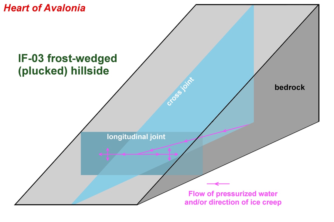
The blue areas shown in the above diagram represent joints that carry pressurized water/ice to a site of frost wedging. The water/ice flows first along a cross joint, eventually encountering a longitudinal joint intersecting the cross joint at a steep angle. The flow then spreads out into the longitudinal joint as illustrated, subjecting the rock bordering the longitudinal joint to a large total force (pressure integrated over the area of the joint). It is unclear exactly where in this process that refreezing takes place. Here are two key questions: Can ice move through joints or narrow fissures by creep alone (maybe over hundreds of years) or must the pressure be transferred by water in the liquid phase? If the pressure is transferred by liquid water, how can refreezing occur when an overlying glacier blunts the thermal gradient and hinders removal of the heat of crystallization?
If the answer to the first question is "yes", then refreezing is unnecessary. If refreezing must occur, then either a sufficient temperature gradient is present in the glacier to remove the heat of crystallization or else the "liquid" water moving in the joints carries little or no latent heat versus ice (see discussions of ice segregation and the Gibbs-Thomson effect in Technical Note 9, Properties of Ice, Mechanisms for Bedrock Frost Heave, Periglacial Processes).
If the answer to the first question is "yes", then refreezing is unnecessary. If refreezing must occur, then either a sufficient temperature gradient is present in the glacier to remove the heat of crystallization or else the "liquid" water moving in the joints carries little or no latent heat versus ice (see discussions of ice segregation and the Gibbs-Thomson effect in Technical Note 9, Properties of Ice, Mechanisms for Bedrock Frost Heave, Periglacial Processes).
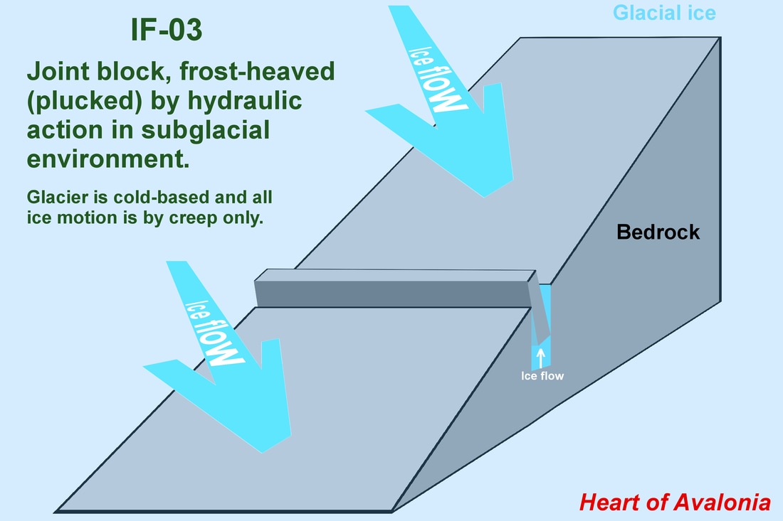
The above diagram provides a schematic representation of the ice motion expected near a frost-heaved joint block on the hill face IF-03. Ice from within the hill moves the block upward and tilts the block forward, as illustrated. Ice moving tangential to the hill face may contribute to tilting the block, but since the tilt is constrained by the surrounding rock, the tangential ice motion would need to be accommodated mainly by creep around the block without adding to the tilt. Furthermore, the blocks were not free to rotate about a vertical axis so as to align with the oblique tangential ice flow. The best evidence for oblique tangential motion of glacial ice over the hill face would be expected to appear in the shifting (horizontal rotation) of unconstrained joint blocks at the base of the hill.
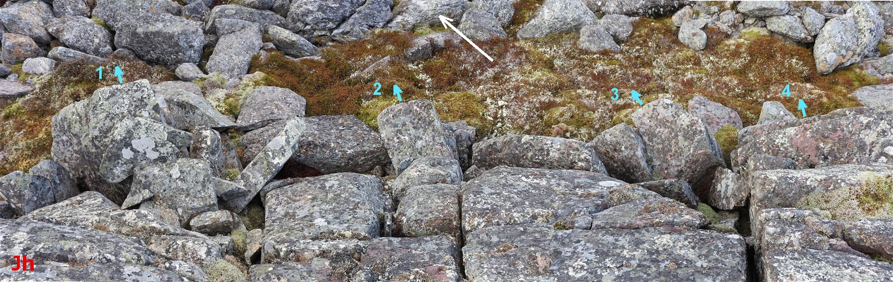
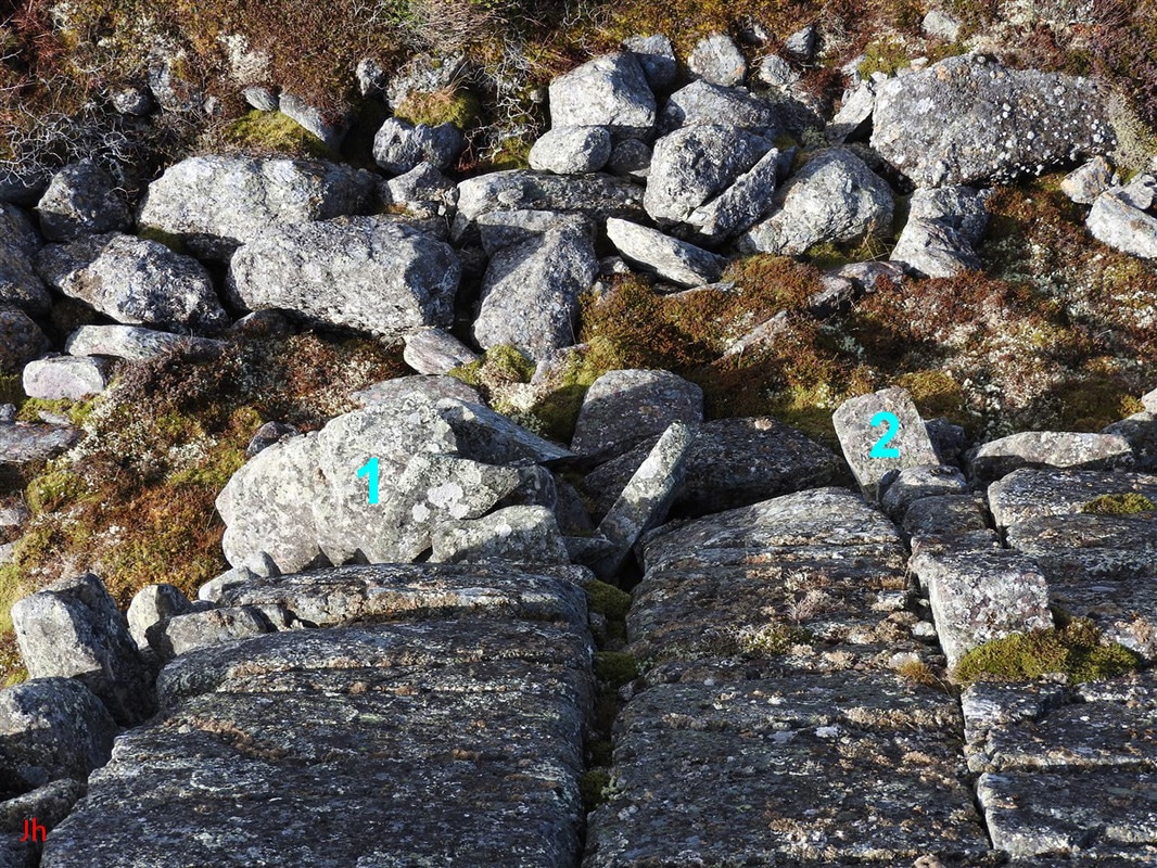
The overhead photo appearing above shows rocks laid out along the bottom edge of the plucked area. The joint blocks labeled 1,2,3 and 4 have all been shifted out of their original alignment with the overlying joint blocks. This could be an example of alignment of blocks by ice creep (Technical Note 7). The overhead photo is oriented such that the major cross joints in the hill strike straight up-and-down as framed in the photograph. Regional ice flow direction is indicated by the long white arrow, while the approximate strikes of the edges (initially defined by major cross joints) of the re-oriented joint blocks are shown with short blue arrows.
|
|
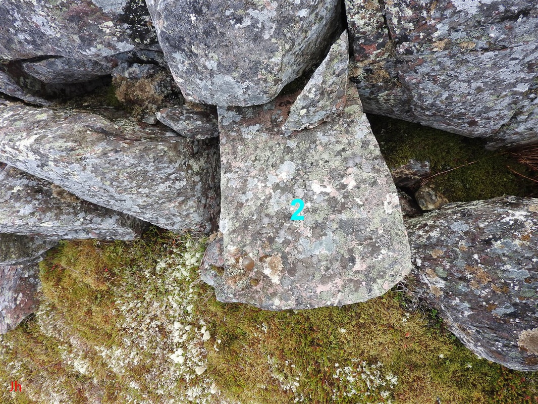
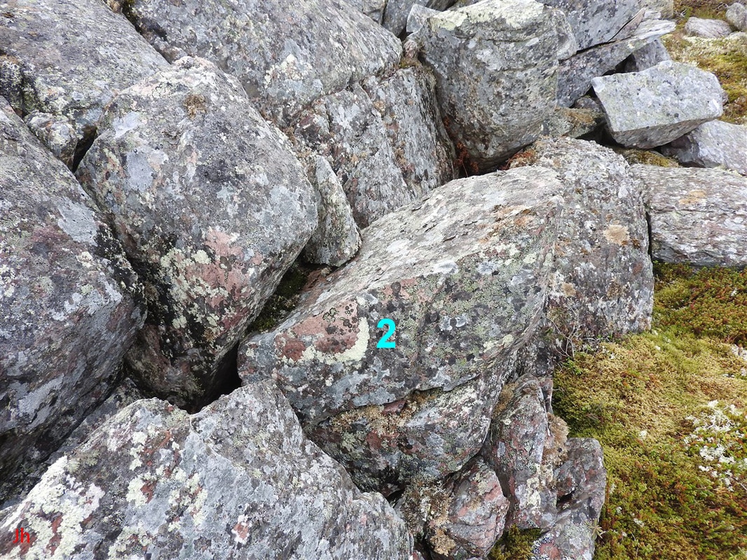
Two closeup views of block 2 are shown above. The photos show how this block was not constrained sufficiently by surrounding rock to prevent its rotation in the horizontal plane. As noted above, most shifted joint blocks in the hill face were constrained from rotating in the horizontal plane.
|
|
The first (left) photo above shows similar re-orientations for blocks 1 and 2, while the second (right) photo shows a closeup of block 1. The angle between the edge of block 1 seen in the second photo and the strike of the fissure immediately to the left (angle change during block re-orientation) was measured at 33 degrees.
The conclusion from these observations is that the realignment of the four blocks shown could reasonably be assumed to have been caused by differential ice creep velocity, with ice further out from the base of the hill moving east-southeast slightly faster than ice closer to the hill. Such a conclusion would support the theory that the blocks were shifted outward from the hill face into a moving glacier and furthermore that the glacier motion was by creep rather than by basal sliding.
The conclusion from these observations is that the realignment of the four blocks shown could reasonably be assumed to have been caused by differential ice creep velocity, with ice further out from the base of the hill moving east-southeast slightly faster than ice closer to the hill. Such a conclusion would support the theory that the blocks were shifted outward from the hill face into a moving glacier and furthermore that the glacier motion was by creep rather than by basal sliding.
Frost heave on the northwest face
The circle drawn in magenta on the above photo surrounds a frost heave feature on the northwest face (plucked area) of the hill, IF-03. The small frost-heaved joint block lies on one of the major cross joints considered as likely conduits of pressurized water/ice responsible for large-scale bedrock disruption at this site. The joint block was probably pushed upward into overlying glacial ice. Two closeups of the joint block are shown below.
|
|
The two pictures shown above are identical except that the second (left) image has been rotated clockwise by 45 degrees. The purpose of the illustration is to show how this shifted joint block seen on the face of IF-03 resembles a normal occurrence of frost-heaved bedrock. The block protrudes 33 cm above the hill face.
|
|
A view of the southeast edge of the plucked area is shown in the two photos above. The first (left) photo shows a major cross joint, widened into a fissure, with several frost-heaved joint blocks visible, extending upward from the fissure. Note how the lifted joint blocks appear shifted to the right (southeast) as would be expected given glacial ice movement downward and east-southeasterly across the face of the hill. The second (right) photo shows a frost-heaved joint block extending up from the fissure, viewed side-on. The hammer is 27 cm long.
The two examples presented above indicate frost heave action that has shifted small, individual blocks almost straight upward, above the plane of the hill face. Many more examples were present where large blocks were shifted upward by frost heave, although in most cases these blocks were also tilted as would be expected given the greater confinement on the uphill side of the blocks than on the downhill side. The overall conclusion was that ice pressure at the base of the shifted joint blocks exceeded ice pressure above the blocks and that the upward shifting of the blocks implies a flow of ice upward from the joint system inside the hill. This analysis, if valid, provides a model for explaining nearby observations of (apparently subglacial) frost-heaved bedrock occurring on horizontal surfaces.
The two examples presented above indicate frost heave action that has shifted small, individual blocks almost straight upward, above the plane of the hill face. Many more examples were present where large blocks were shifted upward by frost heave, although in most cases these blocks were also tilted as would be expected given the greater confinement on the uphill side of the blocks than on the downhill side. The overall conclusion was that ice pressure at the base of the shifted joint blocks exceeded ice pressure above the blocks and that the upward shifting of the blocks implies a flow of ice upward from the joint system inside the hill. This analysis, if valid, provides a model for explaining nearby observations of (apparently subglacial) frost-heaved bedrock occurring on horizontal surfaces.
Transfer of pressure
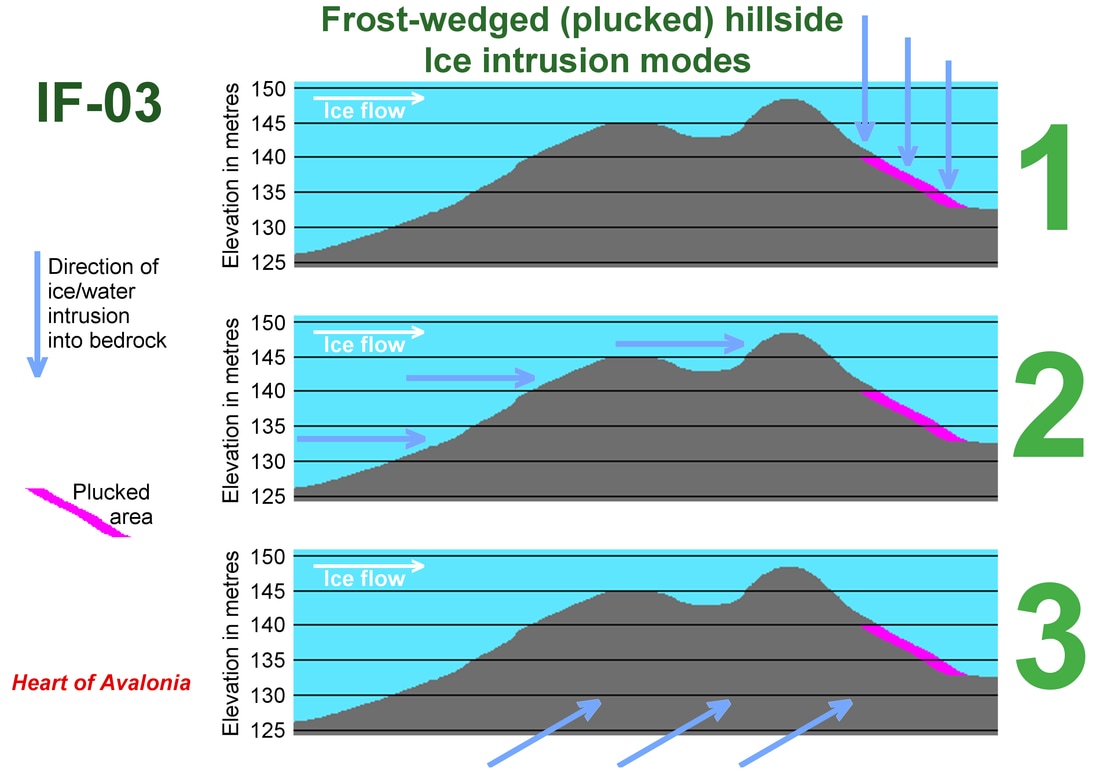
The diagram above presents three possible ice intrusion modes for groundwater/ice to enter the joint system in the bedrock of the hill IF-03 and thereby cause plucking on the northwest face. The hill outline as shown reflects the elevation profile along a path directed 255 degrees true, passing over the top of the hill. The occurrence and location of the plucked area most probably reflects low relative ice pressure in the lee of the hill, which is assumed to lie under a thick glacier. Ice intrusion mode 1 suggests glacial ice entering longitudinal joints on the southwest face of the hill (plucked area) as the ice descends. This mode, while representing a minimum requirement to move ice/groundwater through the hill's joint system, is improbable in light of the above-noted upward displacement of shifted bedrock.
Ice intrusion mode 2 suggests the conventional view of plucking whereby ice, pressurized by the requirement to divert over and around the obstructing hill, melts, traverses the joint system and re-emerges on the lee side where low relative ice pressure facilitates refreezing. This model precludes an overlying cold-based glacier, since pressure melting can only occur at ice temperatures very near 0 degrees C, unless pressures are extreme. If the overlying glacier were temperate, then basal sliding could reasonably be expected to smooth and obliterate many of the features seen on the northwest face, and/or to carry significant amounts of plucked bedrock far down-ice. Essentially all of the bedrock plucked from the northwest face was shifted 1 meter or less.
Ice intrusion mode 2 can account for the plucking observed on IF-03 if a creep-based model is invoked, with cold ice entering and penetrating the bedrock and re-emerging where ice pressure is lower. In this model, the potential mechanism for transport of cold ice through narrow joints and fissures is unclear. The time frame for the occurrence of the observed bedrock disruption is also unclear, but, if extending throughout the Younger Dryas cold period, could have involved a duration of more than a thousand years. Given cumulative rock shifts of only one meter, required groundwater/ice velocities are very low (~1 mm rock displacement per year).
Ice intrusion mode 2 fails when attempting to explain bedrock disruption features seen near the hill, IF-03, but external to the plucked area. These nearby, and possibly related features will be discussed following.
Ice intrusion mode 3 reflects groundwater/ice entering the regional bedrock joint system at a location remote from IF-03 where ice pressure was potentially higher under a steeply sloping glacier. At depth, it becomes reasonable to assume that bedrock temperature reaches the ice melting temperature, a consequence of earlier climatic conditions favoring warm-based glaciation. In this polythermal glaciation model, the glacier overlying the center of the Isthmus of Avalon remains warm-based throughout most of the Younger Dryas because of its thickness, whereas the thinner downstream glacier overlying IF-03 becomes cold-based. This ice intrusion mode allows free-flowing groundwater, kept liquid by warm temperature, to conduct up-ice pressure to the base of IF-03, but it remains unclear where refreezing would occur and how the heat of crystallization would be adequately conducted away through thick glacial ice.
Related external features
|
|
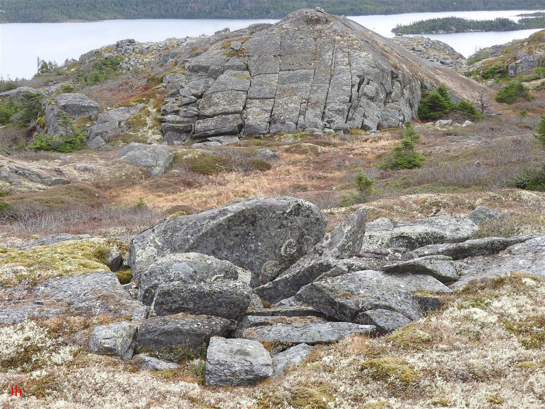
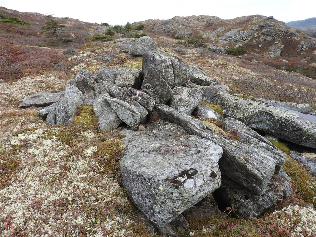
The two pictures above (second is a side view) show a frost-heaved mound, located in front of the IF-03 plucked area. The mound includes several frost-heaved joint blocks, some of these displaced completely clear of the host bedrock. Observations showed that longitudinal joints in the bedrock underlying the mound have been widened into deep fissures. This frost-heave feature lies along the strike of major cross joints traversing the hill, IF-03, seen in the background. Thus the feature might have shared a common pressurized groundwater source with IF-03. Unlike the IF-03 plucked area, there is no reason to assume that glacial ice pressure was diminished by obstructed flow at this location. The frost-heaved mound lies on an up-slope 75 meters from IF-03 and on an ice path which passes north of IF-03. This frost-heave feature could reasonably be interpreted as an example of subglacial bedrock frost heave driven by hydraulic action in response to the same source of pressure that drove the plucking seen in the background hill. If this description is correct, then the existence of this feature supports the model "Ice intrusion mode 3" presented above.
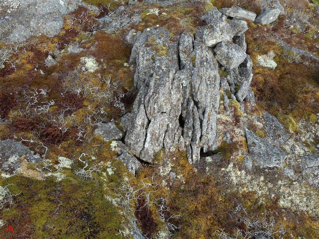
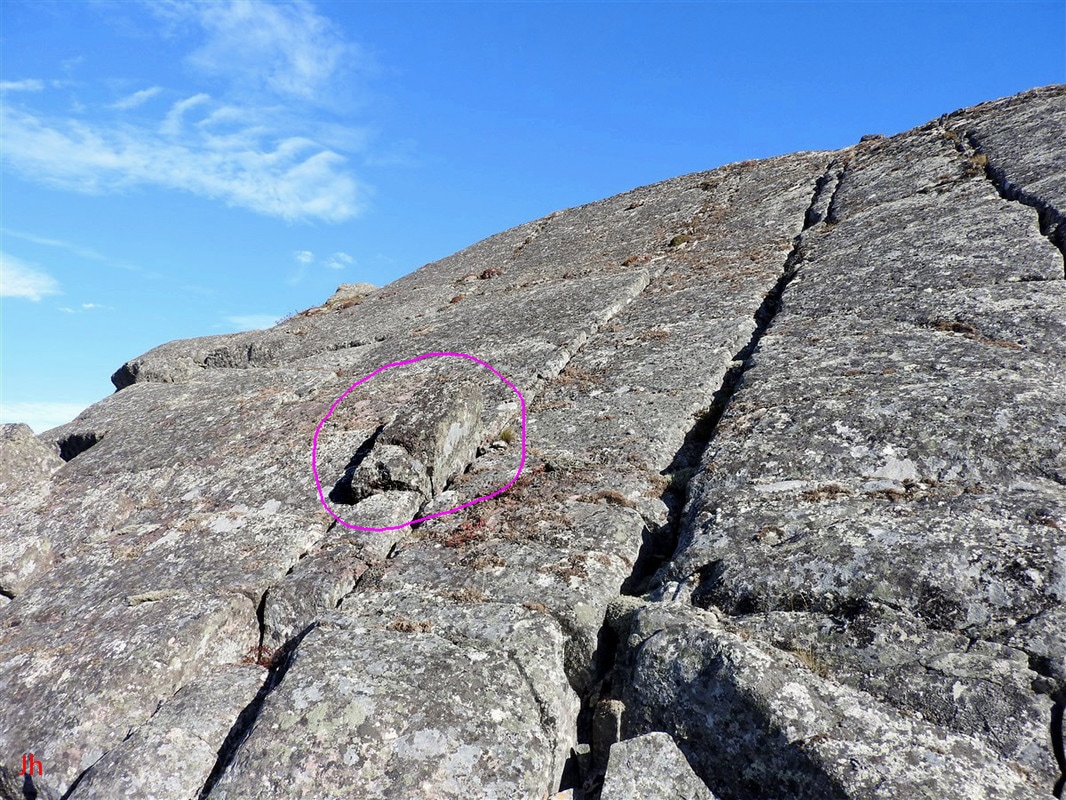
The bedrock feature seen just above center in the above overhead photo is a small (3 meters length, top-to-bottom as framed on photo) outcrop lying almost exactly at the apex of hill IF-03. This feature closely resembles a frost-heaved bedrock feature, although most of the rock has not been noticeably shifted upward. The past presence of pressurized ice is indicated by widened longitudinal joints, fissures and cavities in the bedrock. A further set of four pictures of this bedrock outcrop is presented below.
|
|
|
|
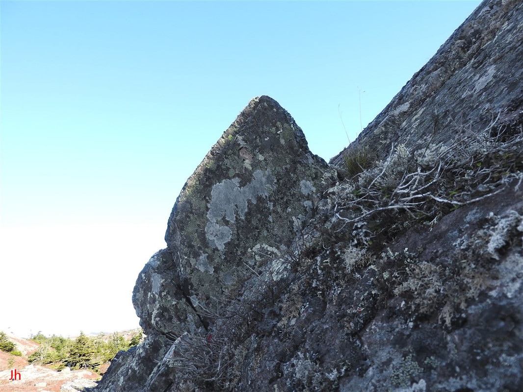
The hammer (hard to see, top of outcrop) in the first (top, left) photo is 27 cm long. Just to the left of the hammer is a slab of rock that is shown close up in the second (top, right) photo. This slab of rock appears to fit into the cavity just below it and has apparently been displaced upward by ice and then rotated 90 degrees in the vertical plane. The bottom two photos show fissures. The measuring tape reads 1.7 m at the point where it bends before going down into the fissure.
This feature can be interpreted to show the effect of ice moving up out of the joint system of hill, IF-03, at the hill's highest point. This interpretation would support "Ice intrusion mode 3" over "Ice intrusion mode 2" as described above.
This feature can be interpreted to show the effect of ice moving up out of the joint system of hill, IF-03, at the hill's highest point. This interpretation would support "Ice intrusion mode 3" over "Ice intrusion mode 2" as described above.
|
|
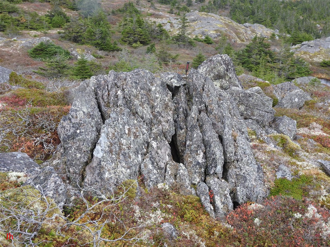
The first (left) photo above shows a bedrock outcrop similar in size and kind to the outcrop described previously occurring at the top of the hill, IF-03. The bedrock has not been vertically shifted in this outcrop, but relict frost-wedge action is indicated by fissures and cavities. This outcrop lies 200 m south of IF-03.
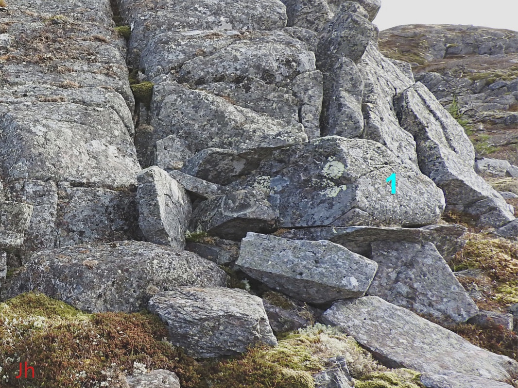
It is significant to propose that a common mode of origin be attributed to the (first, left) above-pictured feature and the subglacial hydraulic frost-heave features discussed previously in connection with IF-03. The significance stems from there being an explicit physical connection between the feature shown in the first (left) photo and the large bedrock frost heave occurrence shown in the second (right) photo. Both of these features comprise part of a single 50 meter long grouping of severely disrupted bedrock features, interconnected with deep fissures paralleling longitudinal cleavage. The second (right) photo shows a frost-heaved monolith standing over 1 meter high alongside large fragments that have been pushed out of the bedrock entirely, then toppled over and seemingly traveled a short distance down-ice in creep-driven glacial flow.
The extensive grouping of bedrock frost heave features and fissures represented by the two photos above, if matching the IF-03 features in origin, could imply that "plucking on a horizontal surface" had occurred over a potentially wide area. This would then make it reasonable to classify hundreds of large bedrock frost heave occurrences, seen over an area in excess of 1 sq. km near the IF-03 site on the Isthmus of Avalon, as having a subglacial hydraulic origin.
In conclusion, the observations presented as Illustrative Feature 3 have been interpreted to further strengthen the case that bedrock frost heave can occur under a glacier and that the phenomenon of subglacial hydraulic bedrock frost heave may be common in some areas of Heart of Avalonia.