Frost-heaved Bedrock: Illustrative Feature 09
Bedrock erosion by subglacial ice extrusion.
Isthmus of Avalon
Bedrock erosion by subglacial ice extrusion.
Isthmus of Avalon
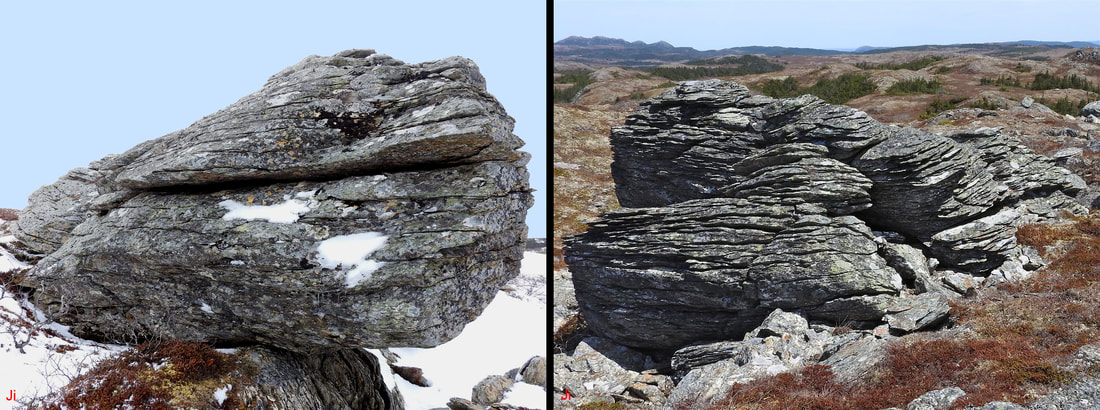
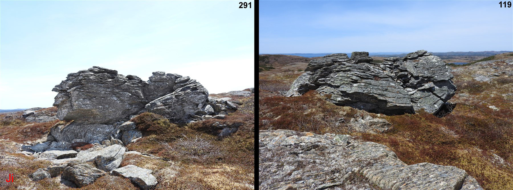
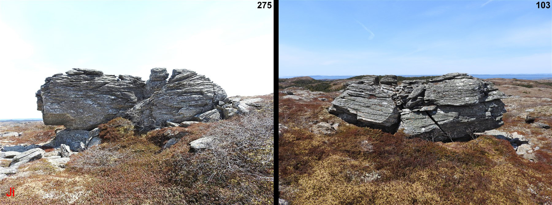
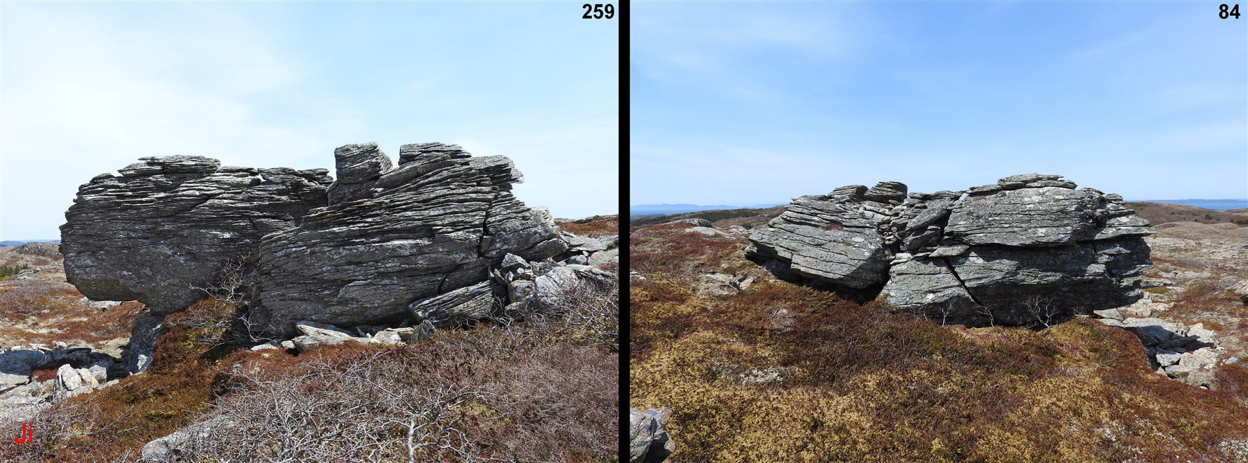
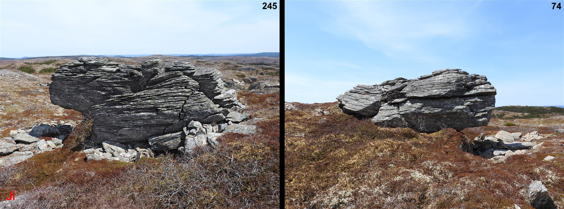
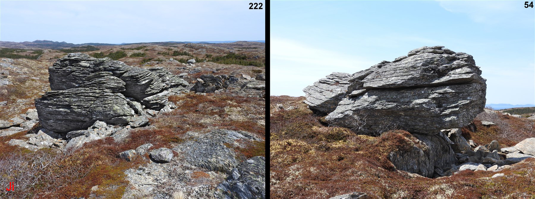
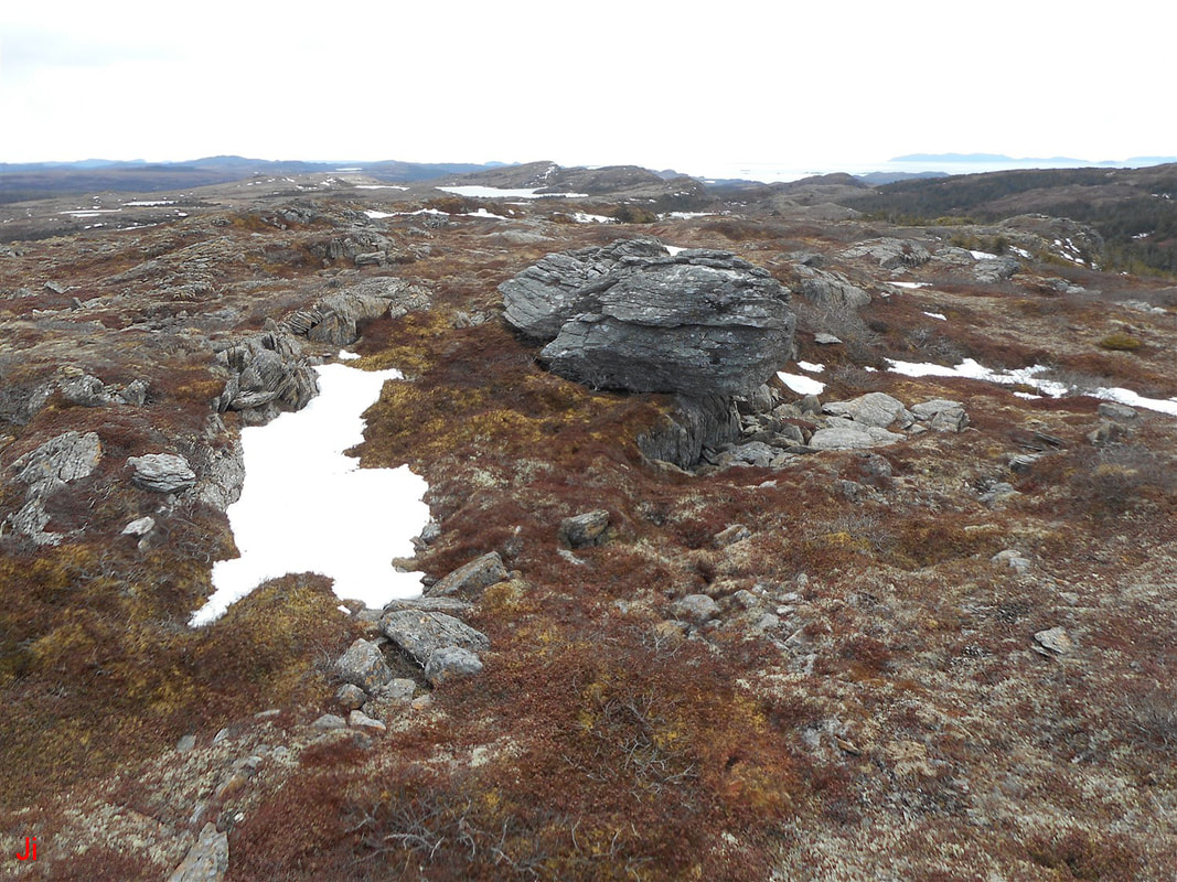
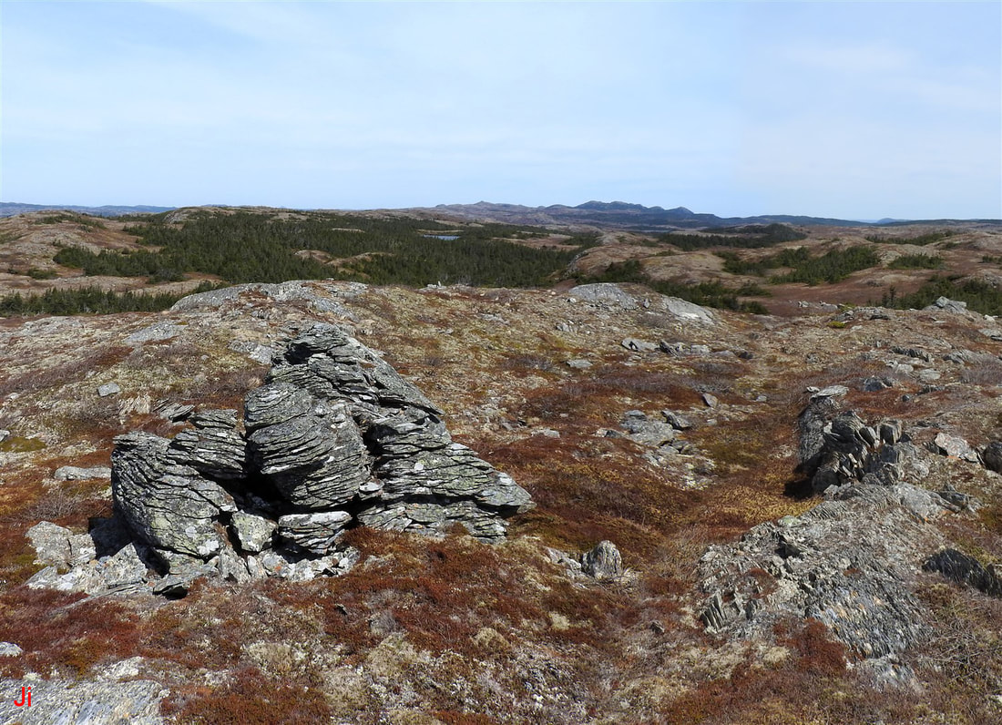
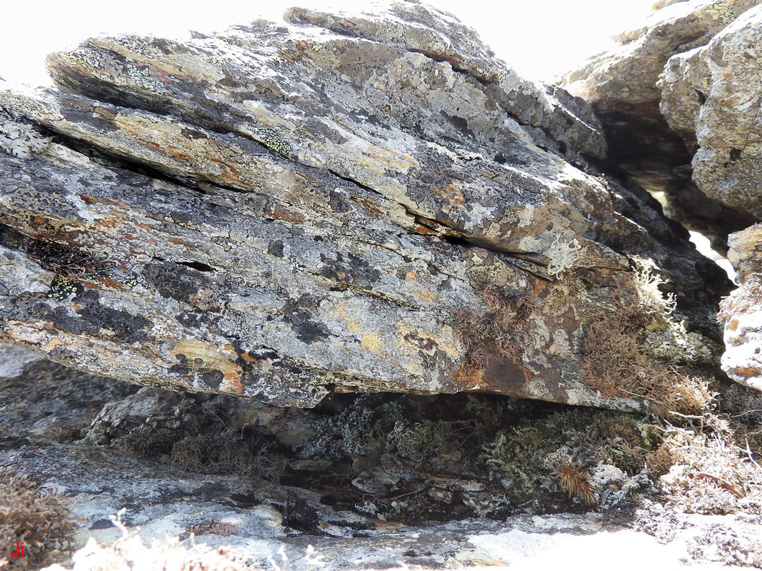
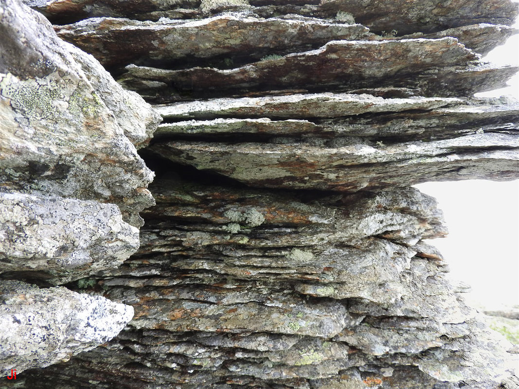
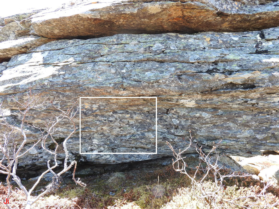
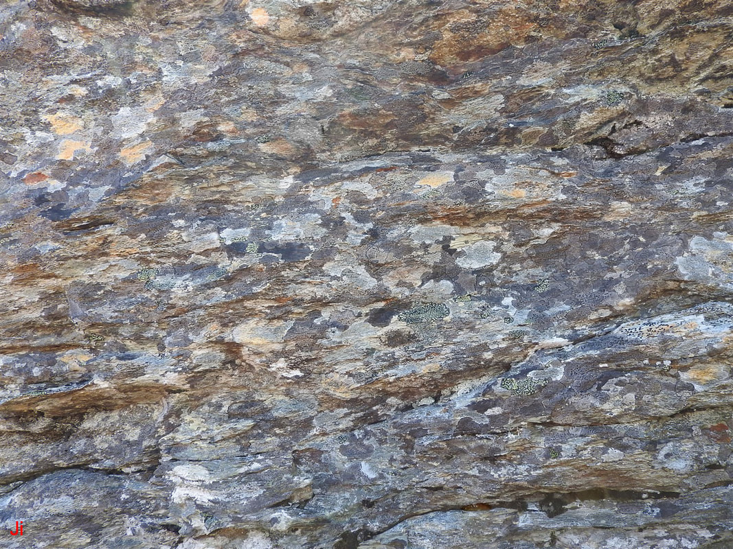
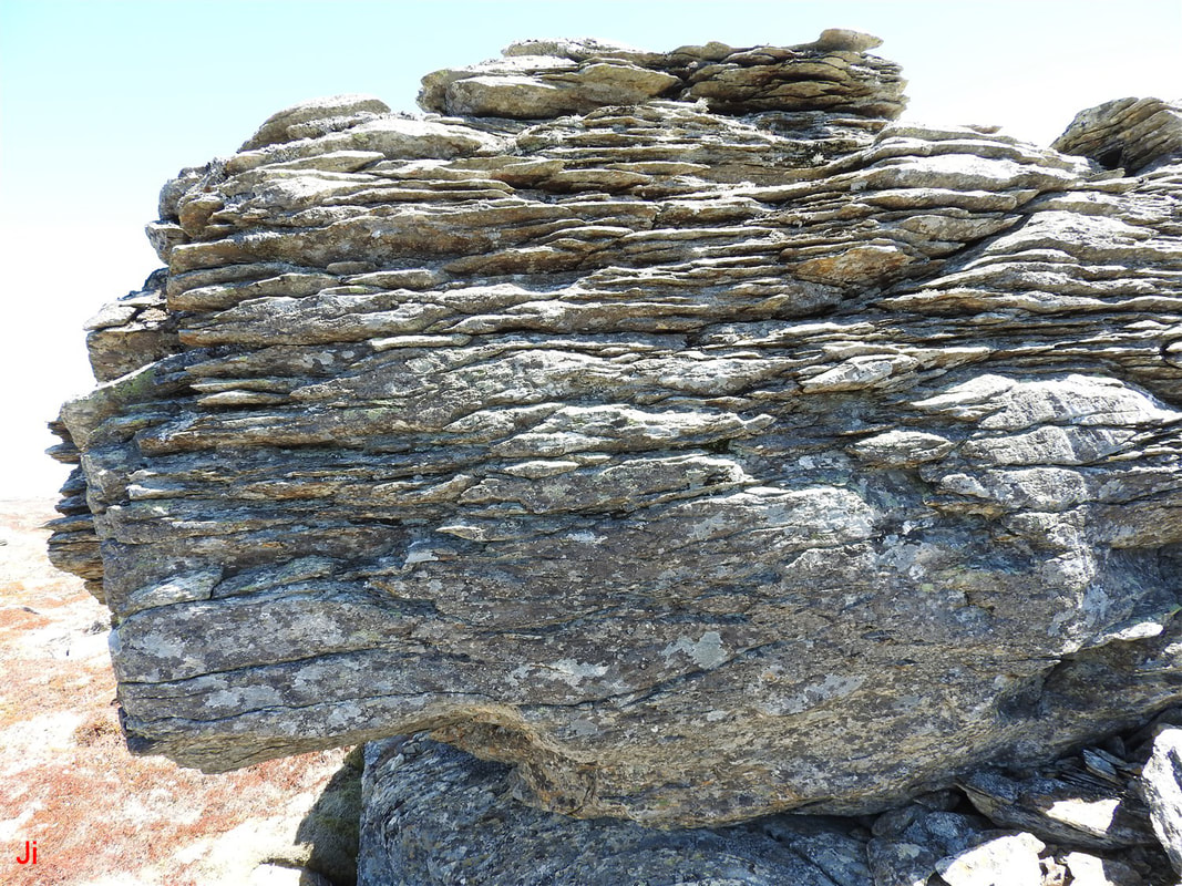
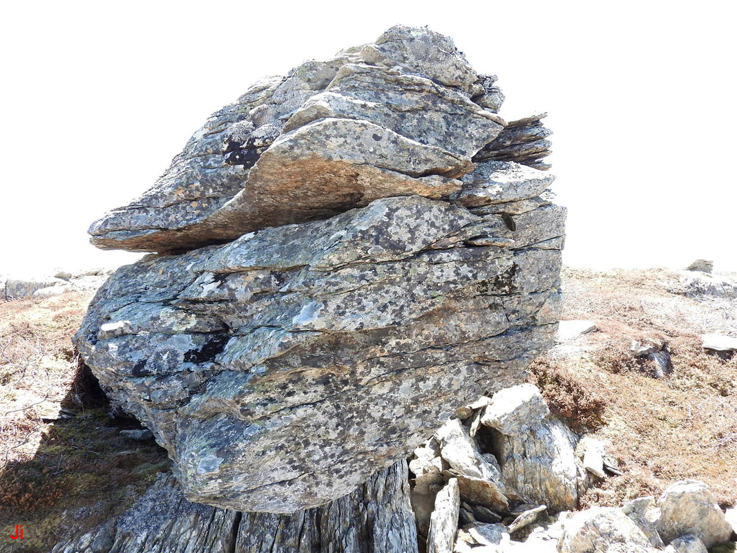
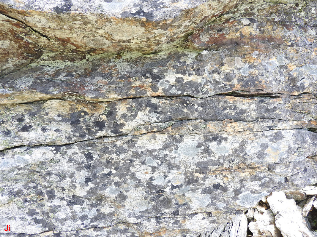
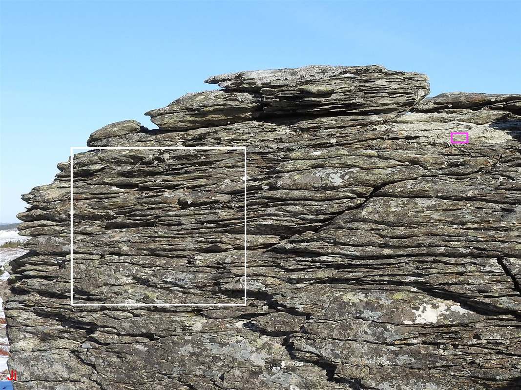
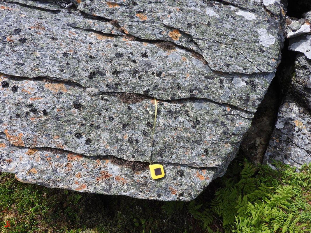
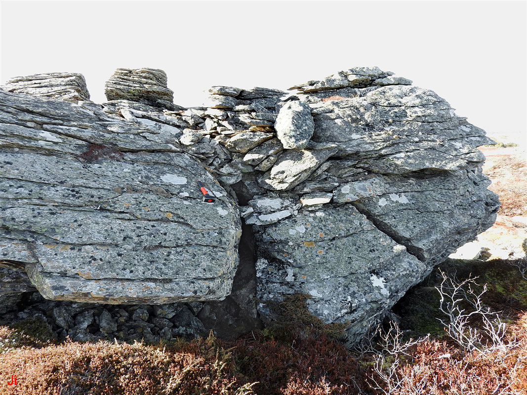
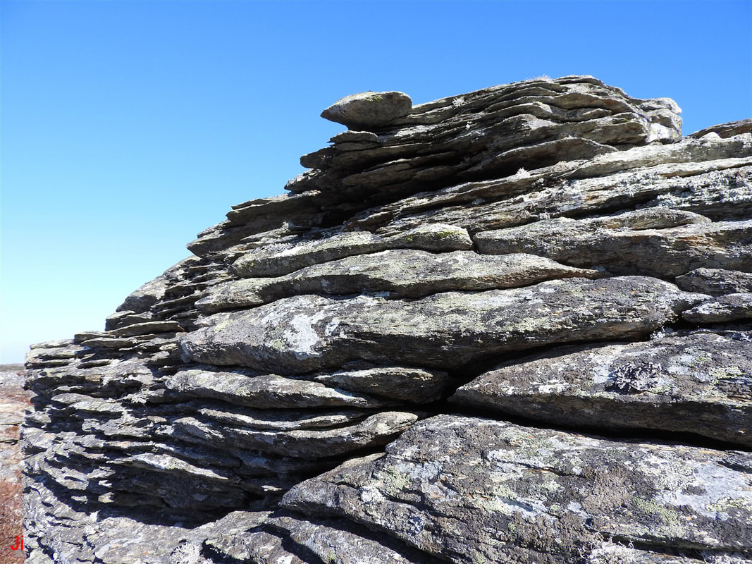
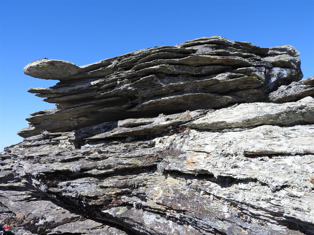
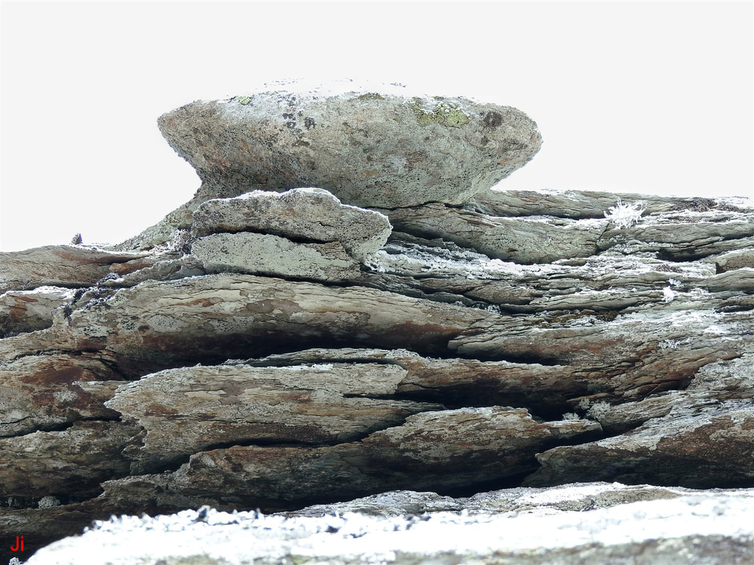
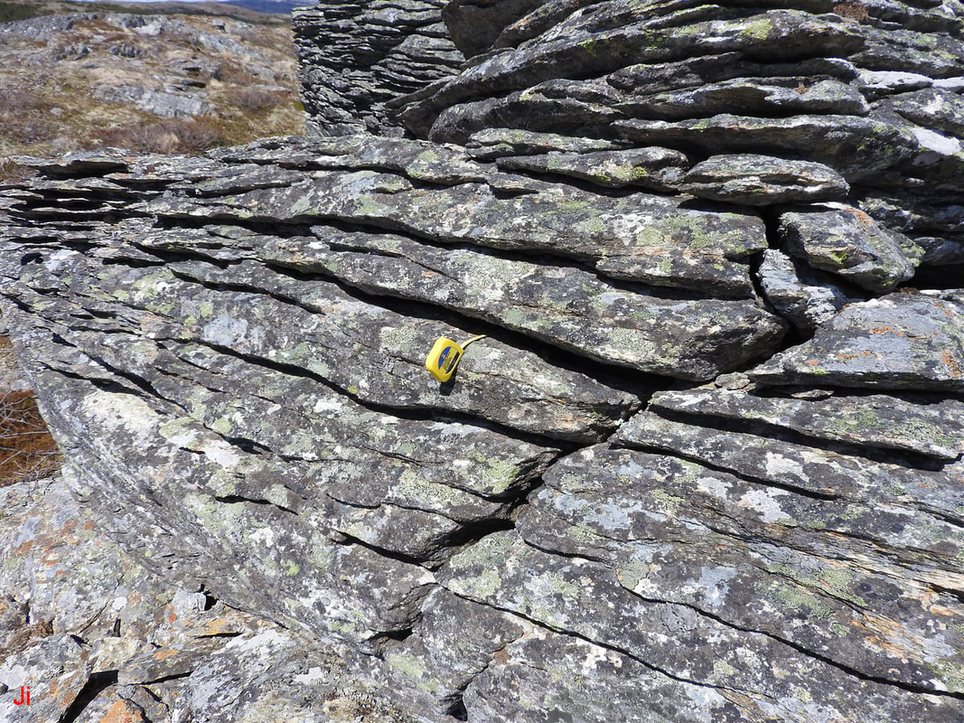
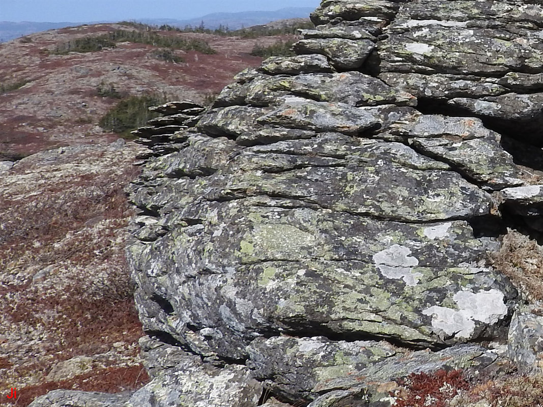
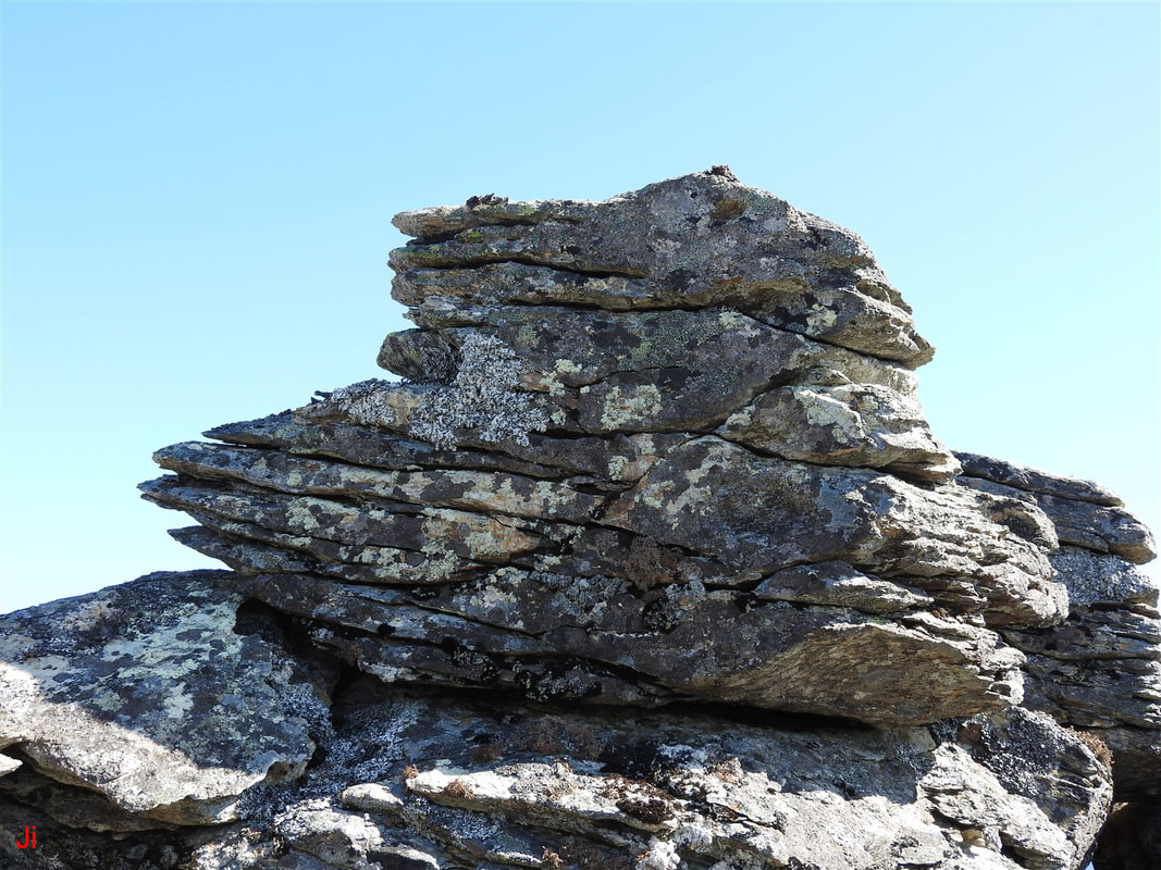
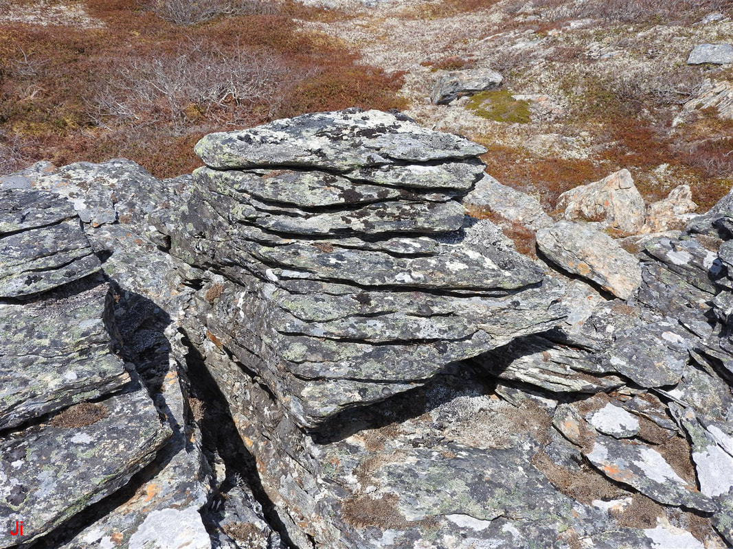
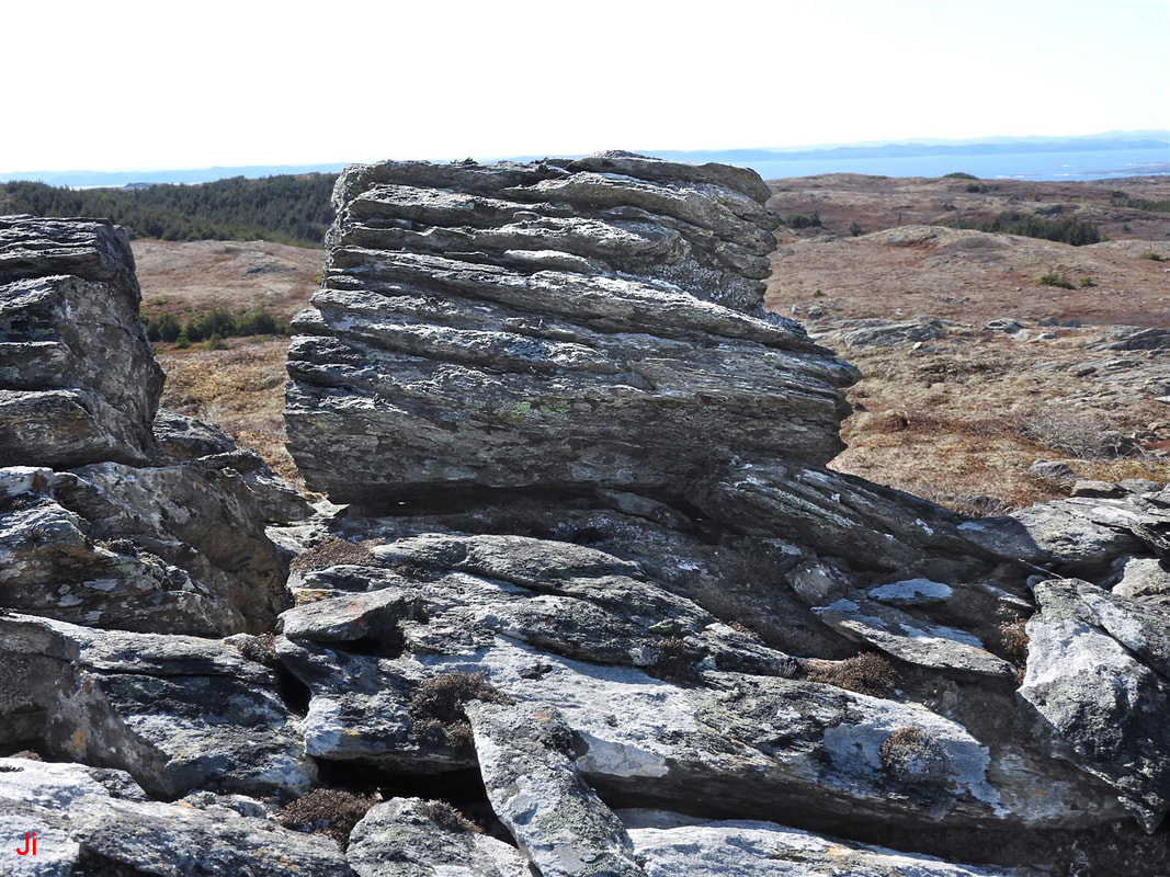
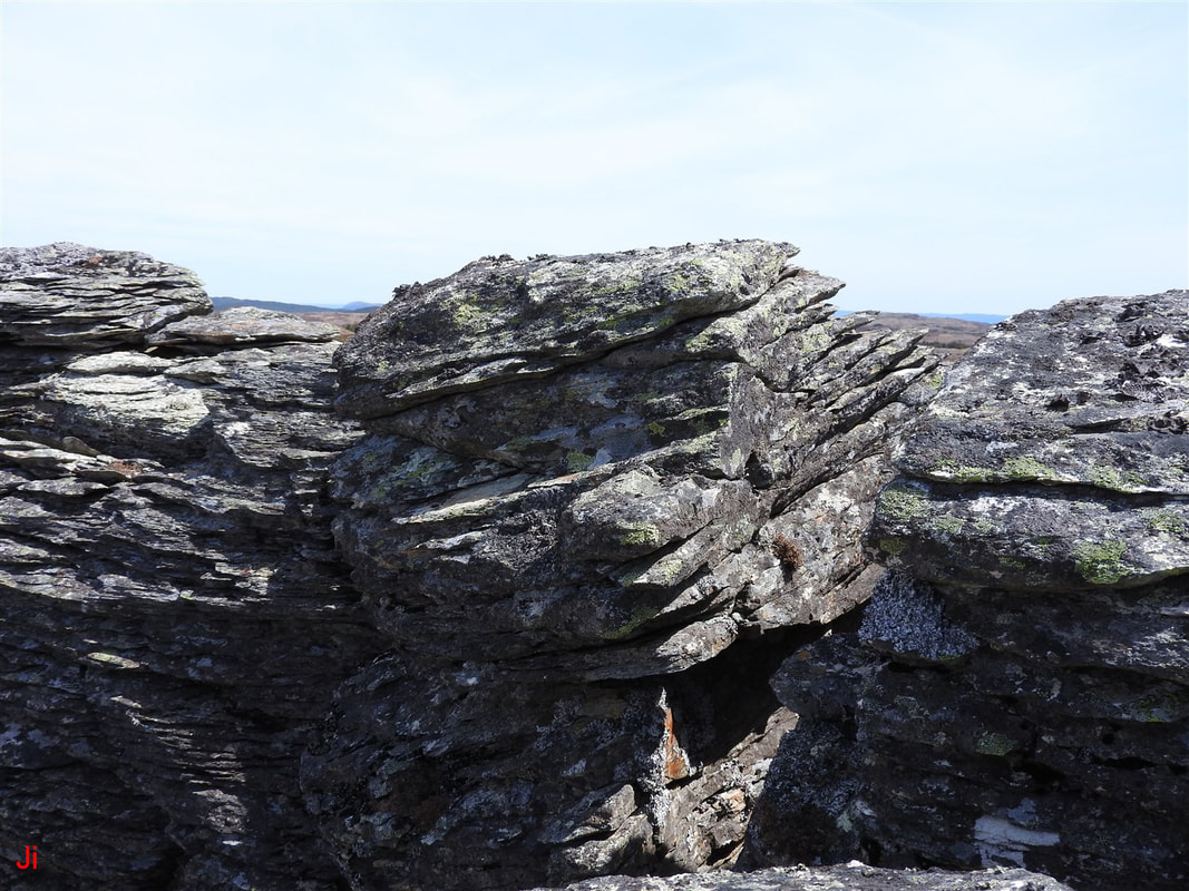
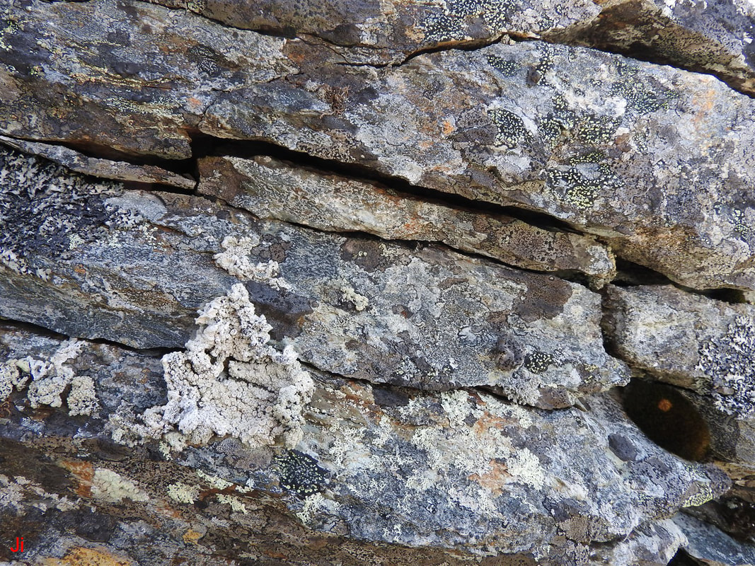
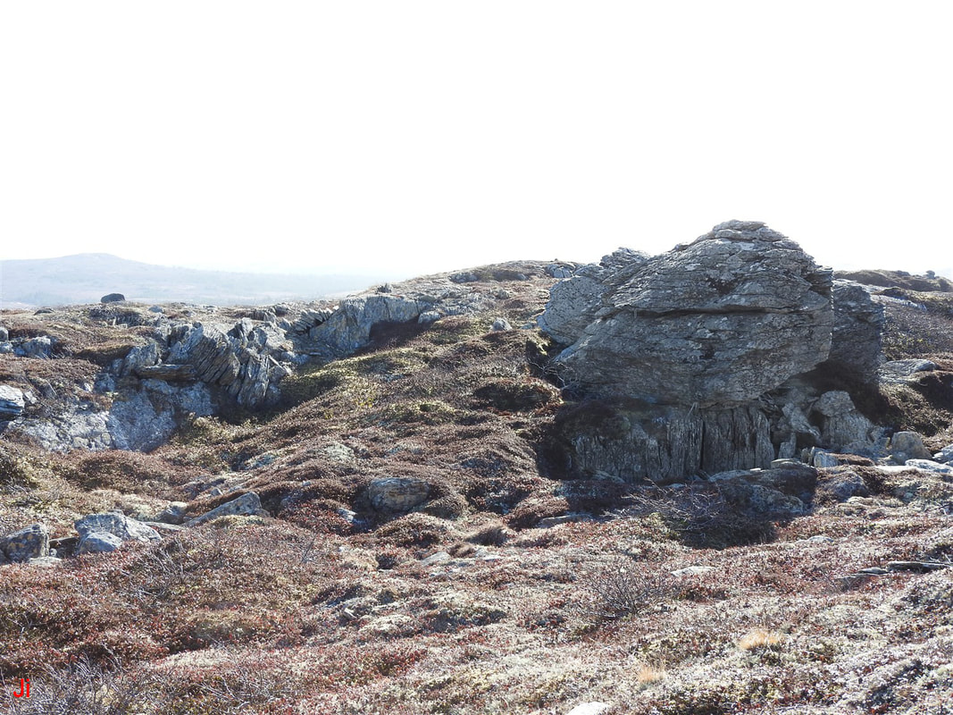
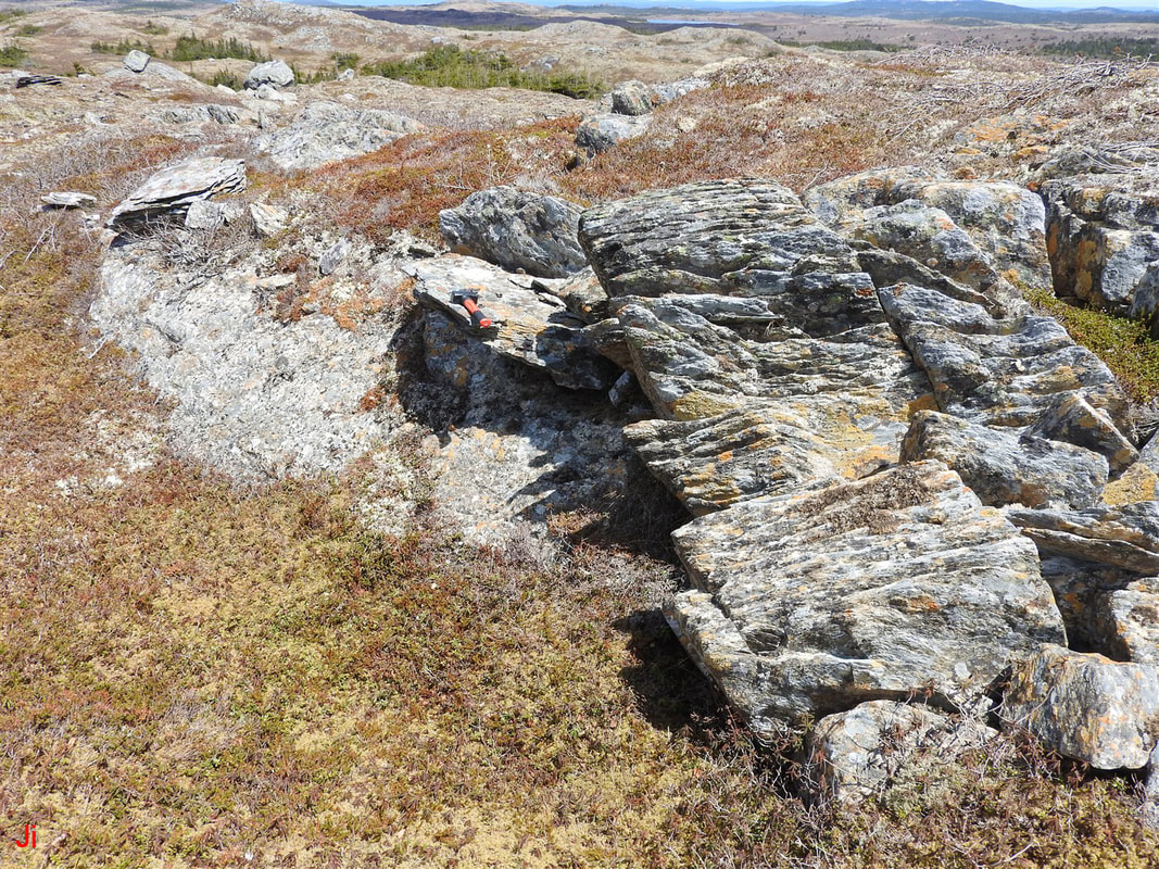
The above photos show 180-degree opposing views of Illustrative Feature 09, a large section of glacially displaced bedrock demonstrating pronounced and asymmetric variations in the erosion of its surfaces. Although eroded asymmetrically, the blocks shown above do not demonstrate any noticeable variation in internal composition or texture. The blocks are comprised of well-indurated, indistinctly-bedded, fine-grained Ediacaran sedimentary rock. Differences in the patterns of erosion seen on opposing surfaces suggest that the erosion occurred under asymmetric conditions. Such conditions would have prevailed in the past, under the assumption that glacial action tore the rock loose from bedrock and caused it to rotate 90 degrees about a horizontal axis. The 90 degree rotation would change originally non-equivalent top and bottom surfaces into present-day symmetrically equivalent side surfaces. This interpretation implies that the asymmetric erosion predates the Holocene and that the erosion features were therefore formed in a subglacial environment. Illustrative Feature 09 provides a continuation of the analysis of ice-induced bedrock erosion patterns introduced in Bedrock Erosion by Subglacial Ice Extrusion - Part 01.
The primary purpose of examining Illustrative Feature 09 is to further investigate the idea that characteristic erosion patterns can be used to identify areas where ice has been extruded from bedrock in a cold subglacial environment. A secondary objective is to look for possible artifacts that might indicate the mode of internal movement of ice and water through frozen bedrock. IF-09 was deemed suitable for analysis because it can be shown with a high degree of confidence, that the large body of rock comprising the feature was shifted less than 10 meters from its bedrock origin and was rotated approximately 90 degrees about a horizontal axis by glacial mechanical action and/or settling. The glacially shifted group of blocks preserves a pattern of erosion features that can be plausibly correlated back to an episode of subglacial erosion that occurred before the blocks were separated from bedrock.
The following discussion will be divided into three main sections. First, evidence of the glacially-induced shift of the position and orientation of the blocks comprising Illustrative Feature 09 will be presented. Second, examples of erosion patterns on the blocks and the asymmetry and spatial variations in the erosion patterns will be provided. Third, the indications of observable effects of ice or water having moved through frozen bedrock will be discussed.
The following discussion will be divided into three main sections. First, evidence of the glacially-induced shift of the position and orientation of the blocks comprising Illustrative Feature 09 will be presented. Second, examples of erosion patterns on the blocks and the asymmetry and spatial variations in the erosion patterns will be provided. Third, the indications of observable effects of ice or water having moved through frozen bedrock will be discussed.
Geographic overview
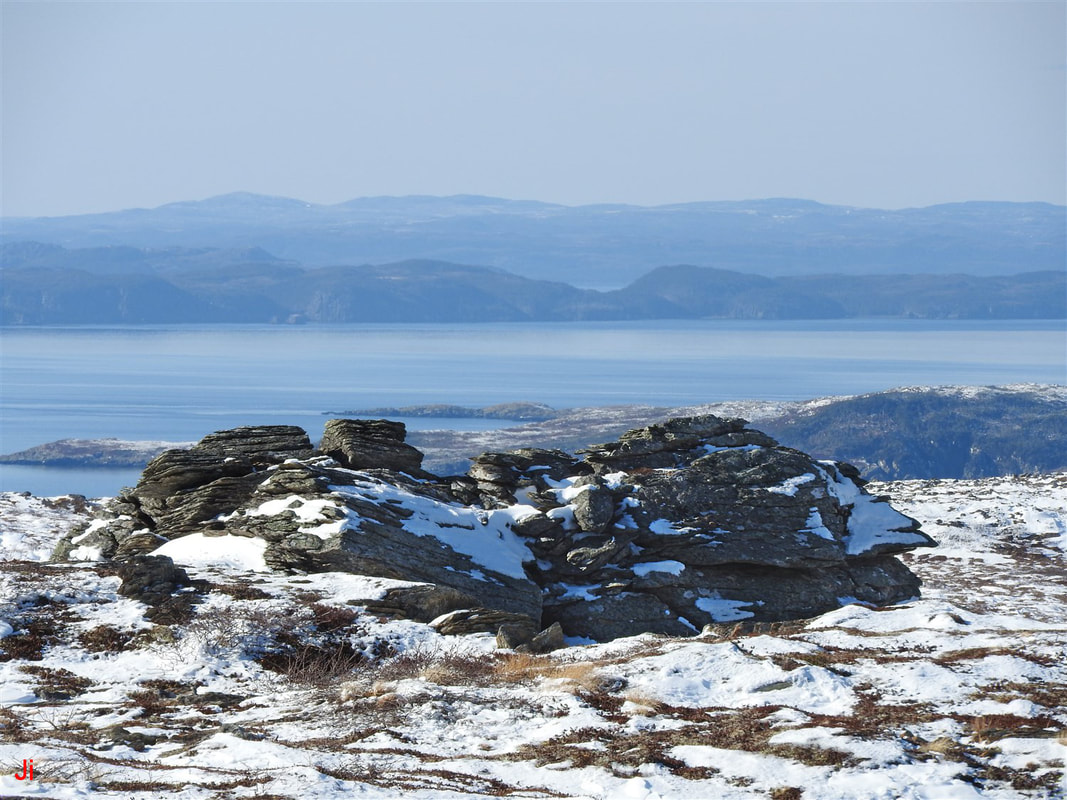
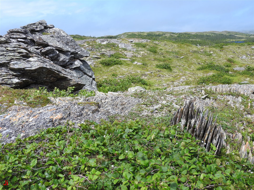
IF-09 sits near the north edge of the top portion of a glacially rounded and glacially plucked hill about 3.8 km from the coast of Placentia Bay on the Isthmus of Avalon. The feature is 180 m above present sea level. The preceding telephoto exaggerates the apparent proximity of IF-09 to the coast.
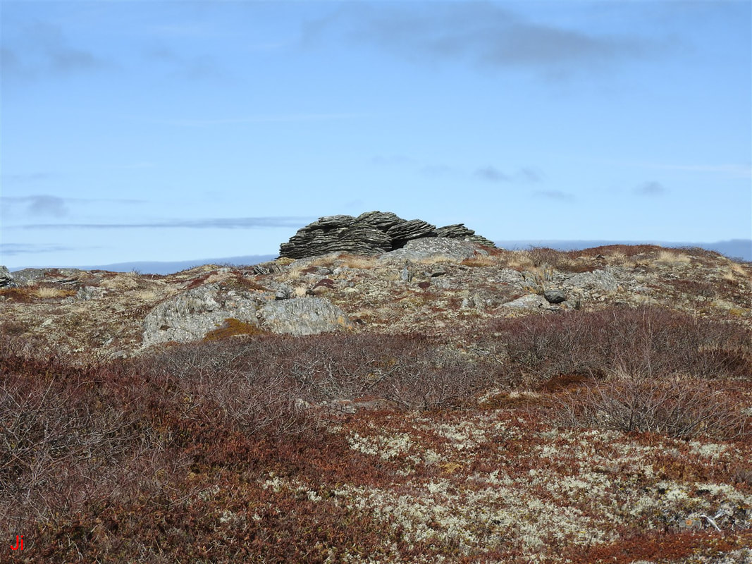
The view shown above, taken from north of IF-09, shows IF-09 protruding just noticeably above the line of the horizon at the upper left of the frame. The hill hosting IF-09 includes glacially-eroded cliffs on the north-west slope. These cliffs show evidence of plucking by warm-based glacial ice flow. The cliffs have subsequently been modified by cold-based glacial erosion and they incorporate substantial areas of ice-disrupted bedrock characterized by rock shifts of the order of 1 meter or less. The upper slopes of the hill and the top portion of the hill possess abundant occurrences of ice-disrupted bedrock, including numerous frost-heaved monoliths.
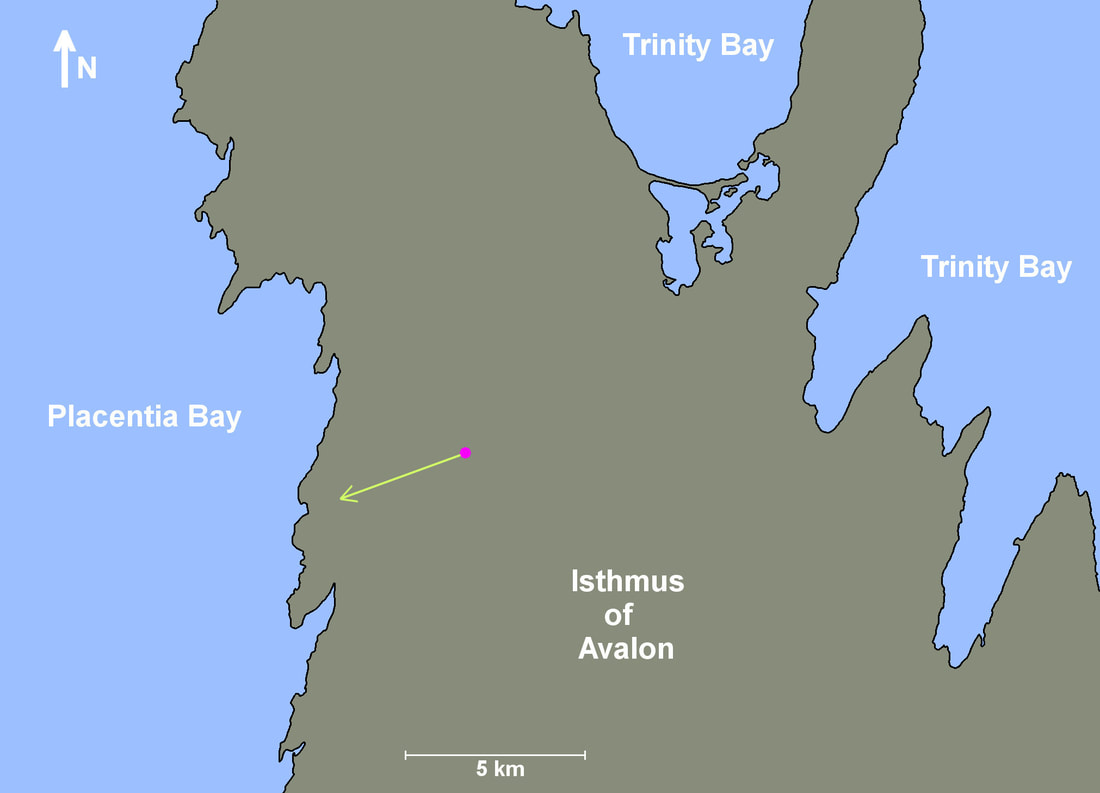
The location of IF-09 on the Isthmus of Avalon is indicated by the magenta dot on the above map. The arrow extending toward the coast from the IF-09 location indicates a direction of inferred glacial ice movement. However, the arrow does not reflect the sliding of warm-based glacial ice. Rather, the indicated direction shows the trend observed in shifts of fragments of ice-disrupted bedrock. Many of the observed fragments were shifted via rotation about a horizontal axis. In other instances fragments or blocks were dislodged from bedrock and translated horizontally by a few centimeters or meters. The arrow shows what is thought to be a dominant direction of near-ground creep of cold glacial ice.
Note regarding interpretation of cold-based glacial ice creep near the ground:
Field observations from this Project (Heart of Avalonia, Frost-heaved Bedrock) provide indications that after subglacial bedrock had been disrupted by ice it was then subjected to shift by shear stress imparted by an overlying deforming cold glacier. As ice deforms in creep near the ground, bedrock that is frozen to the ice becomes exposed to elastic shear-loading at the ice-rock interface. The bedrock can then fail in tension when it is not sufficiently laterally confined by surrounding rock. Specifically, lack of confinement on the down-ice side of a section of bedrock will lead to tensile loading of the rock as overlying glacial ice frozen to the rock deforms in creep. If this tensile loading exceeds the strength of the rock, faults will form (both parallel to the ground and orthogonal to the ground), fissures will open and fragments of bedrock will begin to track the near-ground creep deformation in the overlying glacier.
The process described above is enhanced when subglacial bedrock frost heave occurs beneath a glacier that is undergoing deformation by creep near the ice-rock interface. In this instance, bedrock fragments that have been loosened and/or extruded by non-tangential ice flow will become subject to shift by the shear stress generated by the overlying glacier. Fragments can be tilted or translated in a manner that reflects the magnitude and direction of near-ground glacial ice deformation. Rock fragments that are injected deeply into an overlying deforming cold glacier (subglacial ice plume action) can eventually be translated over a significant distance, the end result mimicking transport by a basal-sliding warm-based glacier.
Many examples showing evidence of bedrock shift by cold-based glacial ice creep have been observed within the context of this Project. The process seems common and has apparently occurred over wide areas of ice-disrupted bedrock found on the Avalon Peninsula. Using shifts of bedrock fragments as a guide, directions of near-ground cold-based glacial ice creep can be inferred. However, observations indicate that patterns of ice creep very near the ground (< 1 m) are sometimes surprisingly complex. Rather than indicating a consistent laminar flow over flat topography with diversion around obstructions, rock displacement patterns generated by ice creep sometimes suggest near-ground ice motion that incorporates curving flow paths, flow reversal and potentially, eddies. The possibility that near-ground ice creep can incorporate chaotic ice deformation patterns must be considered when using small-scale bedrock shifts to infer large-scale cold-based glacier motion.
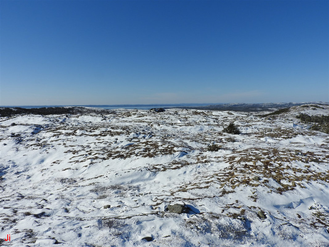
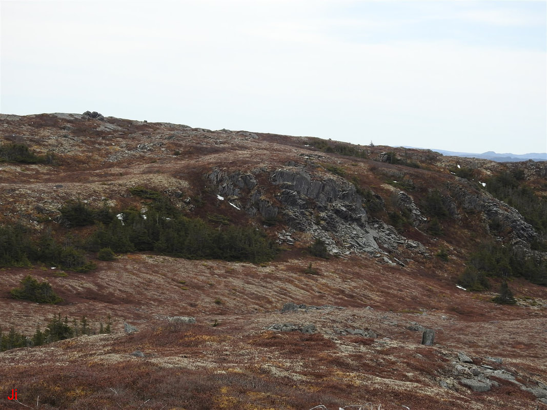
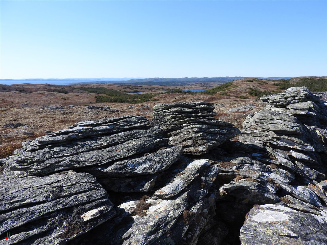
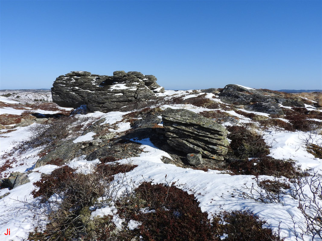
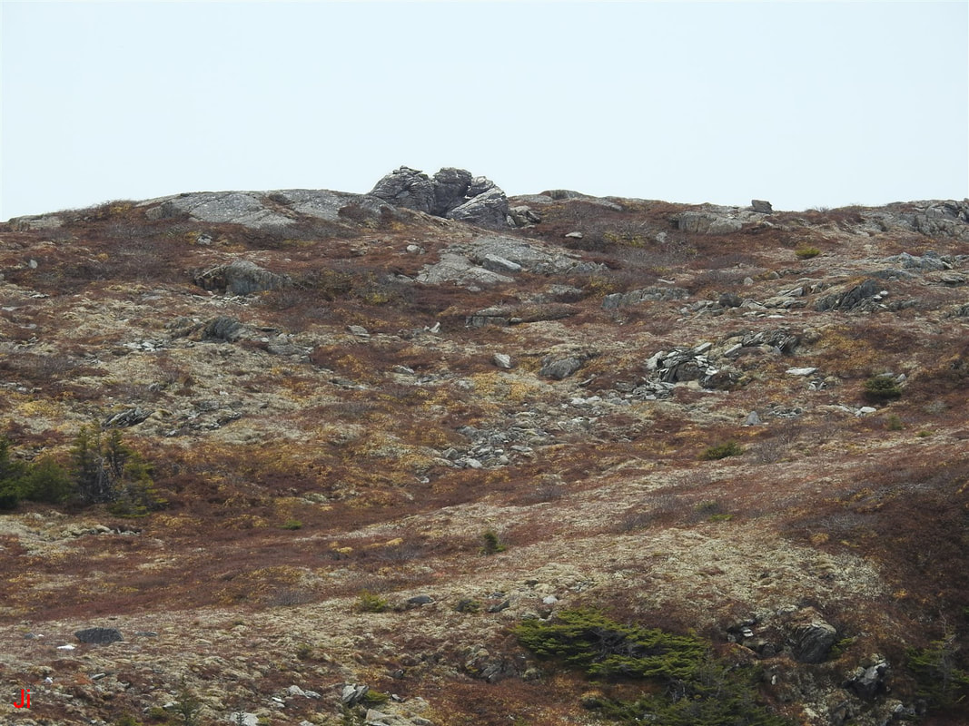
The above photo shows the relatively broad, flat topography of the hilltop southeast of IF-09. The feature of interest, IF-09, is just visible at the horizontal center of the frame, on the line where the snow-covered ground meets the horizon.
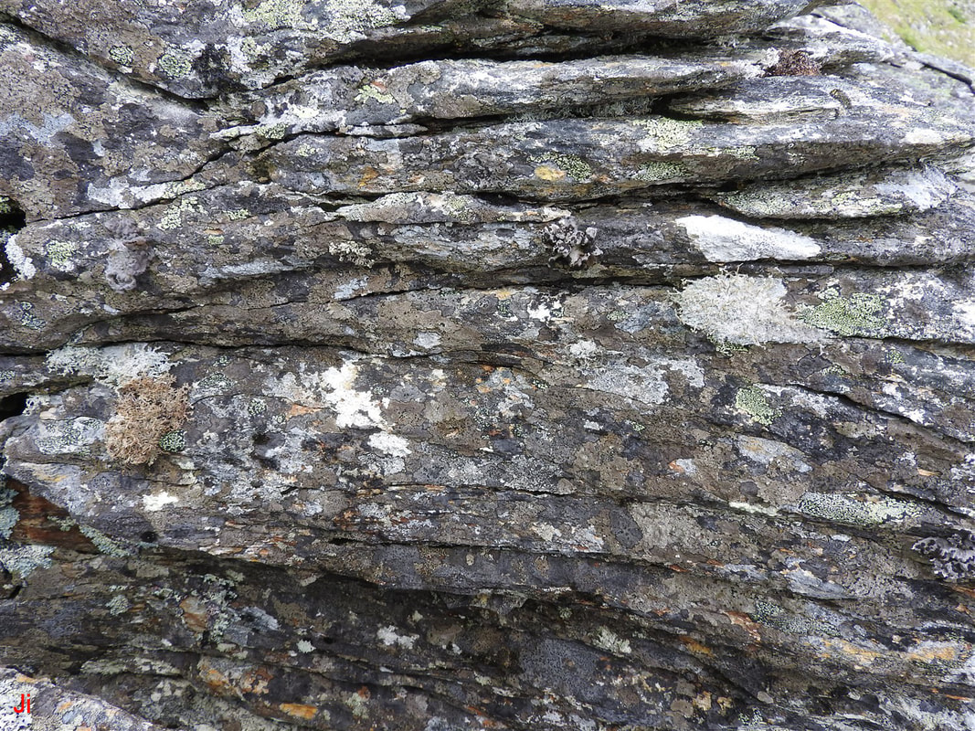
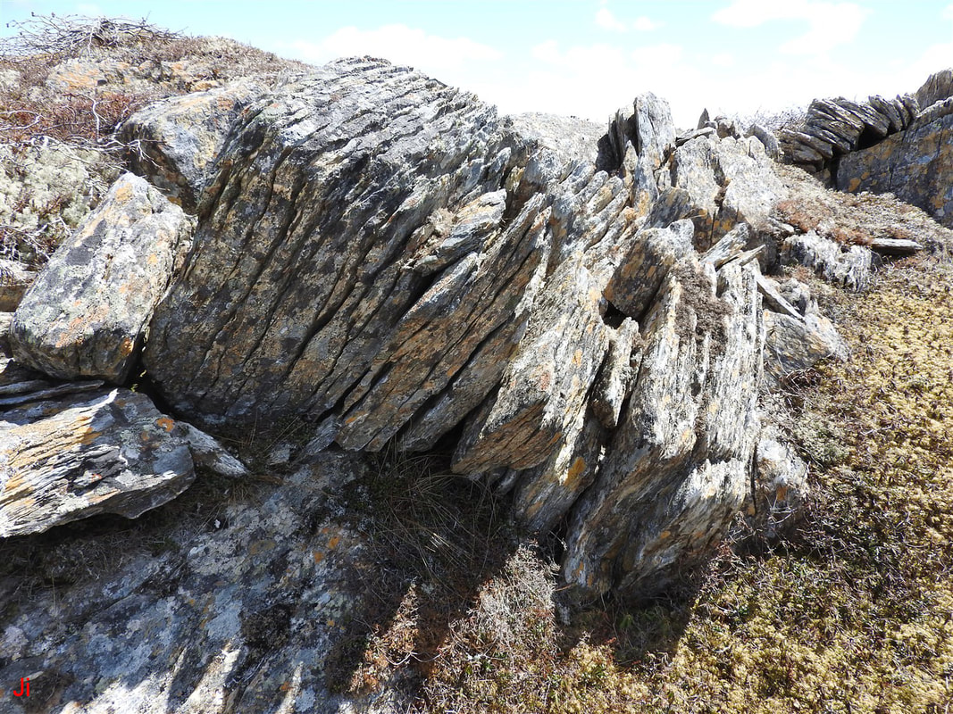
Viewed from the southwest, horizontally aligned grooves eroded into the side of IF-09 are plainly visible. These grooves follow foliation induced in the fine-grained homogeneous sedimentary rock by tectonic compression. The horizontal grooves contrast sharply with abundant erosion patterns seen on nearby bedrock. The nearby bedrock also frequently shows a deeply grooved erosion pattern, but with the grooves always following vertically-dipping foliation. Examples are shown in the photos below and lead to the conclusion that the rock sections comprising IF-09 are detached from bedrock and have been rotated by approximately 90 degrees about a horizontal axis.
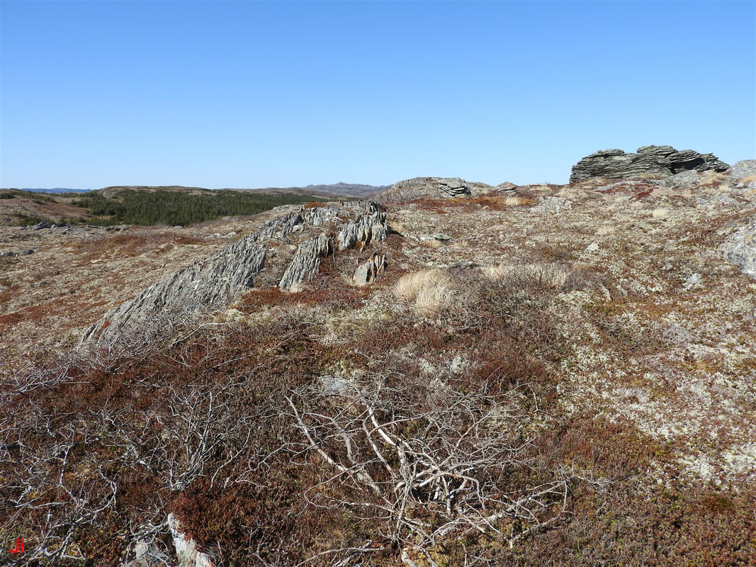
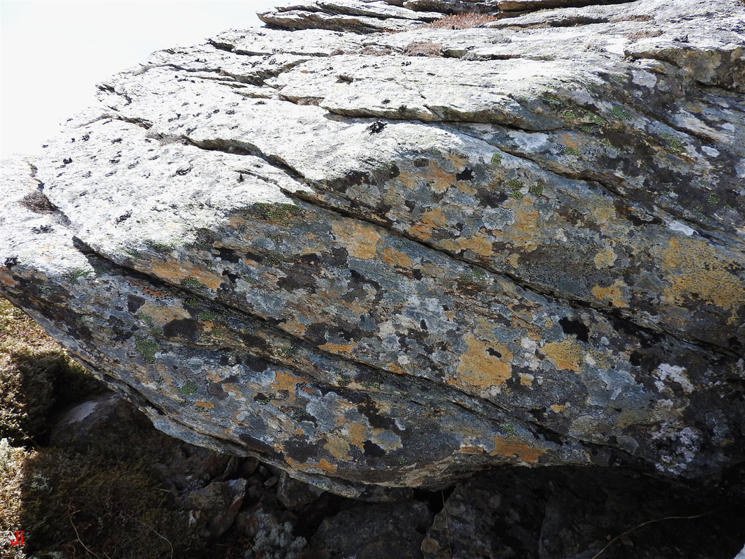
A bedrock outcrop lying southwest (left on photo) of IF-09 is shown above. The grooved, tectonically-aligned erosion pattern seen on this outcrop resembles the erosion pattern seen on IF-09. The eroded grooves follow vertically-dipping foliation in the bedrock. It will be argued in this discussion of Illustrative Feature 09 that the erosion patterns seen in surrounding bedrock share a common origin with the erosion patterns seen on the sides of If-09.
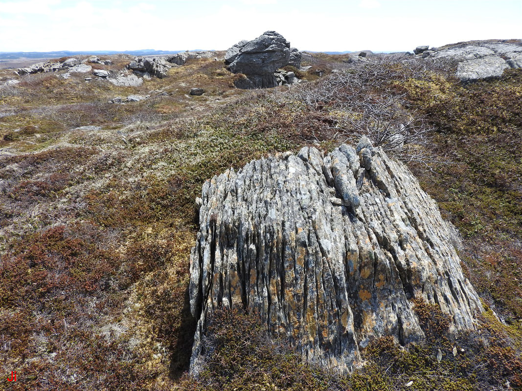
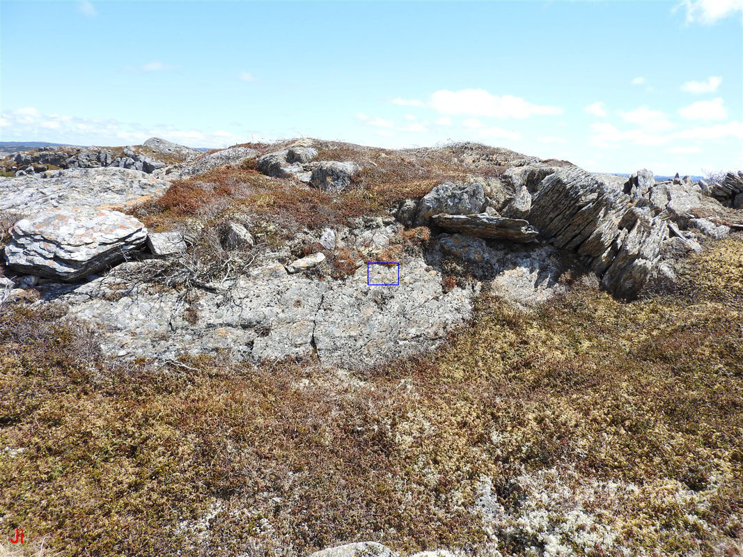
The foreground of the above photo includes an outcrop of bedrock lying north of IF-09. IF-09 is visible in the center background. Not all of the exposed bedrock in the immediate area of IF-09 demonstrates a grooved erosion pattern. The bedrock outcrop appearing at the upper right of the above photo has been smoothed by basal-slip glacial erosion, but lacks the distinctive grooves seen on the foreground outcrop.
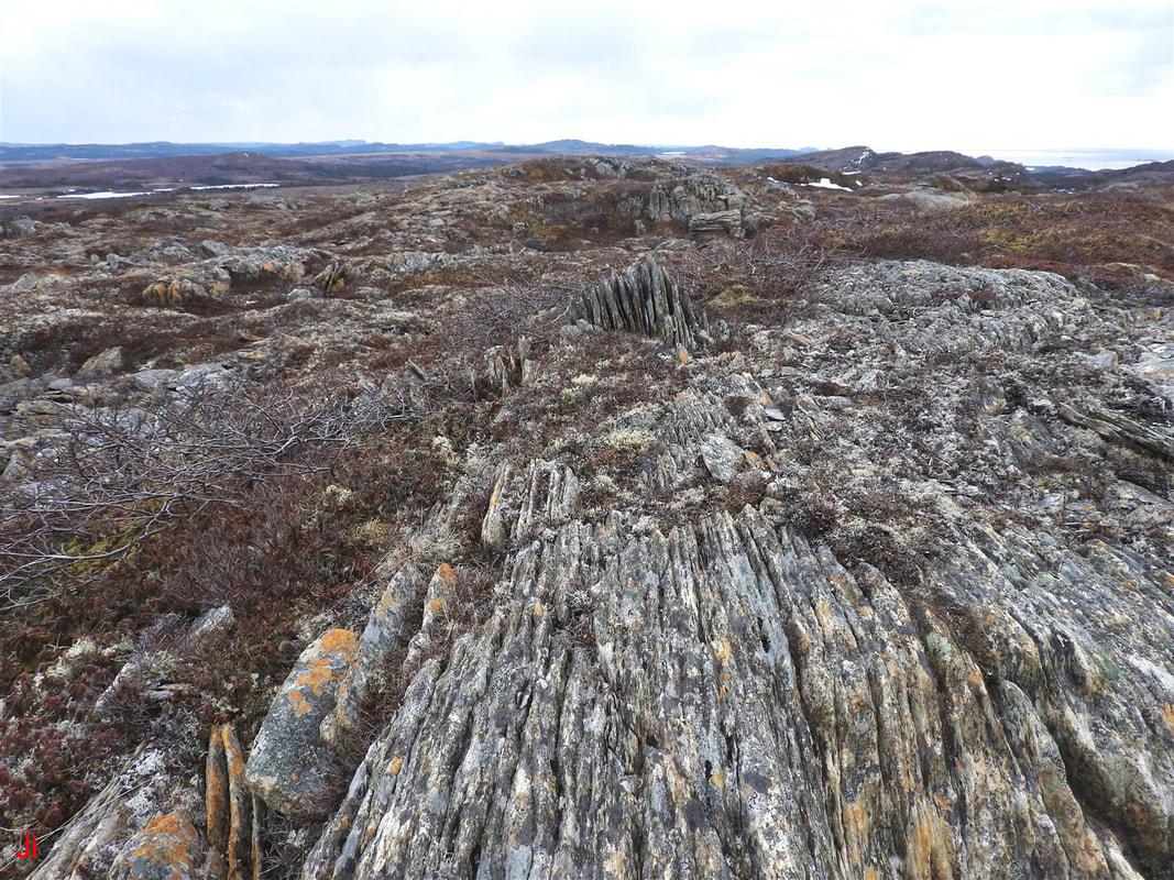
The picture shown above was taken from the location of IF-09, looking south. The heavily grooved bedrock seen in the foreground has been disrupted by ice. Note the small, rotated joint blocks on the left. Just beyond the foreground area of ice-disrupted bedrock is a layered frost-heaved monolith (roughly triangular in profile as viewed above).
Description and layout of IF-09
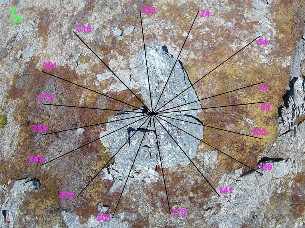
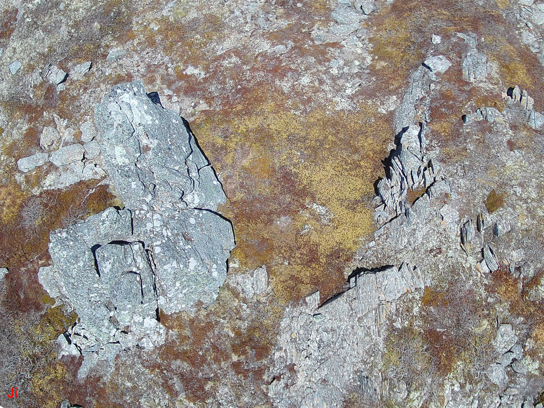
An overhead view of the group of glacially-displaced sections of bedrock, IF-09, is shown above. The group of blocks is about 9 m long (north end to south end) and stands about 1.7 m high at its highest point. Sixteen photos were taken to show a 360 degree view of the feature. The camera positions are indicated by the magenta numbers shown on the above aerial photo. The numbers indicate the compass angle (degrees true) pointing to each camera position from the center indicated on the above diagram.
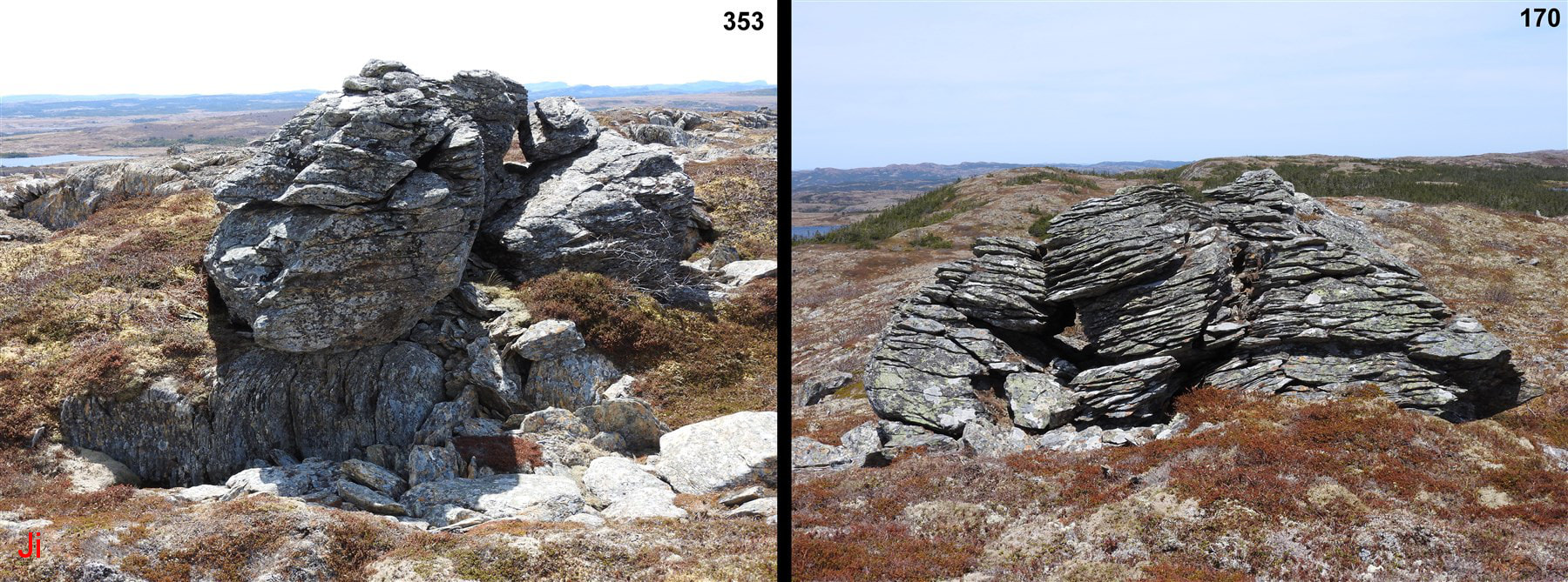
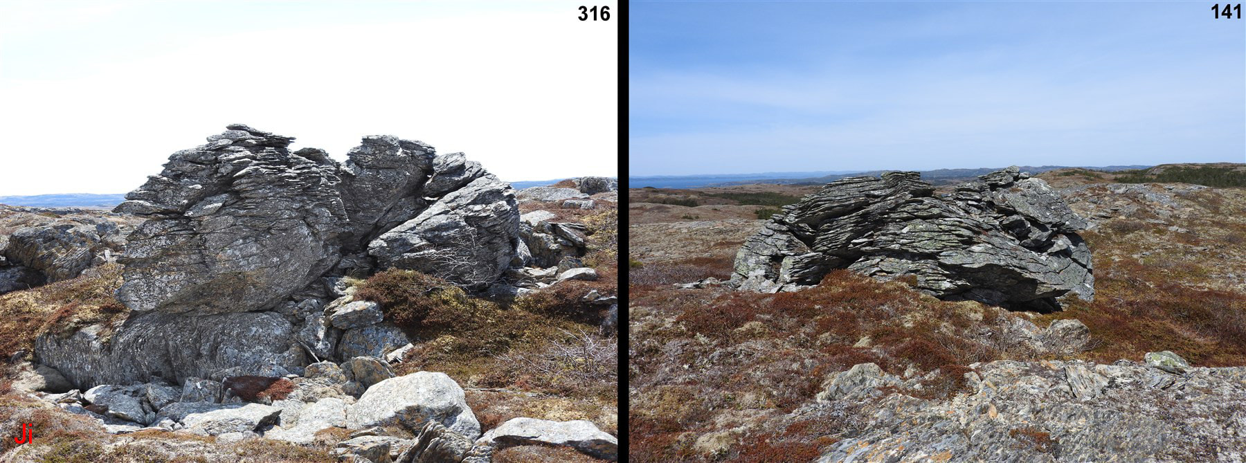
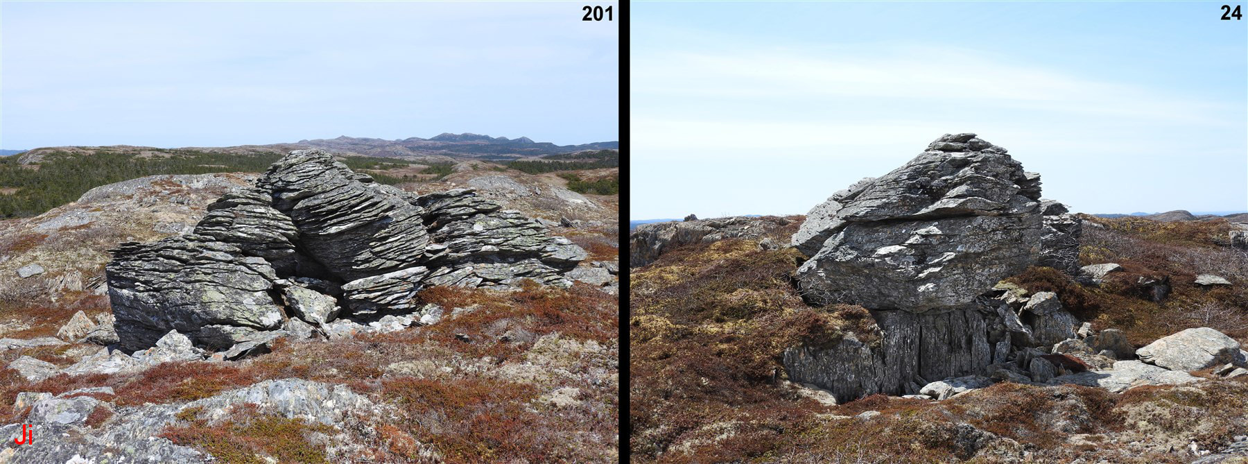
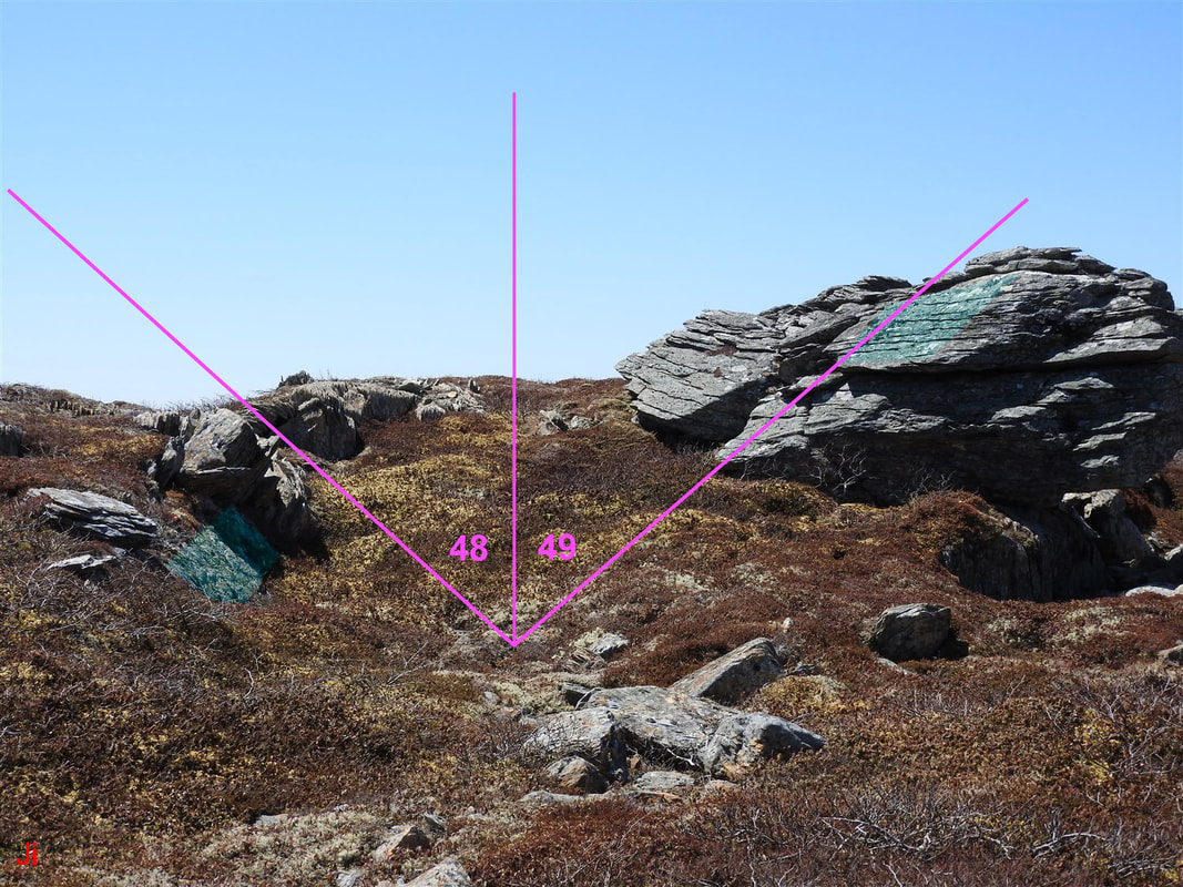
The following sequence of photos shows IF-09 as pictured from the camera positions indicated above. Each photo pair shows the feature as viewed from two approximately opposing directions.
The following sequence of photos shows IF-09 as pictured from the camera positions indicated above. Each photo pair shows the feature as viewed from two approximately opposing directions.
Evidence of Glacial Shift
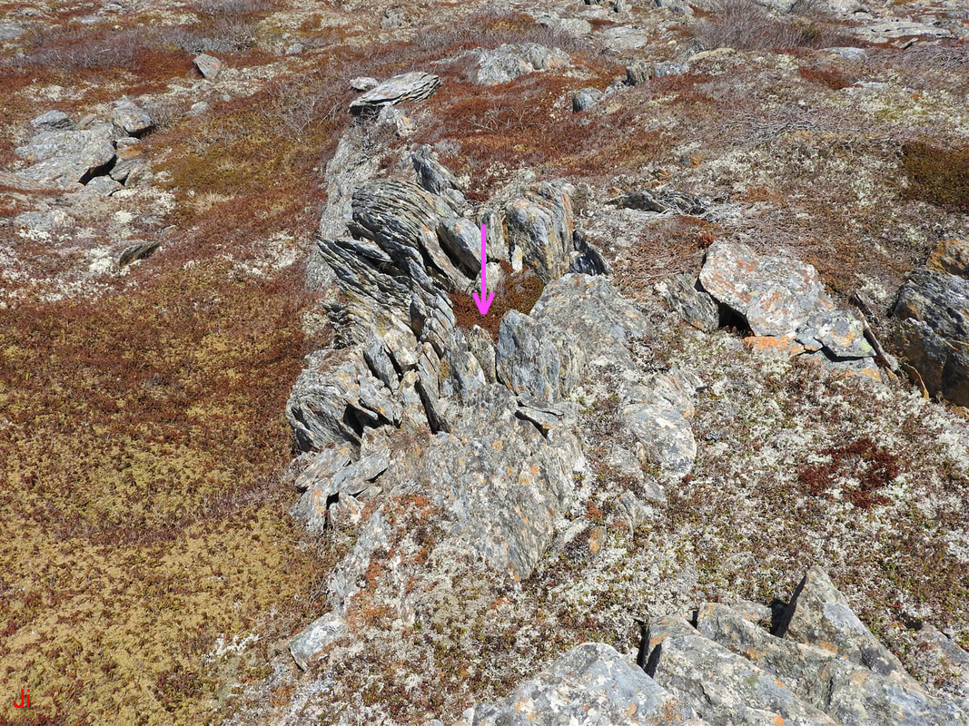
The group of blocks comprising IF-09 appear to have been glacially displaced from nearby bedrock. The photo below shows an overhead view of the displaced blocks and the indentation remaining in adjacent bedrock following their displacement.
The group of blocks comprising IF-09 appear to have been glacially displaced from nearby bedrock. The photo below shows an overhead view of the displaced blocks and the indentation remaining in adjacent bedrock following their displacement.
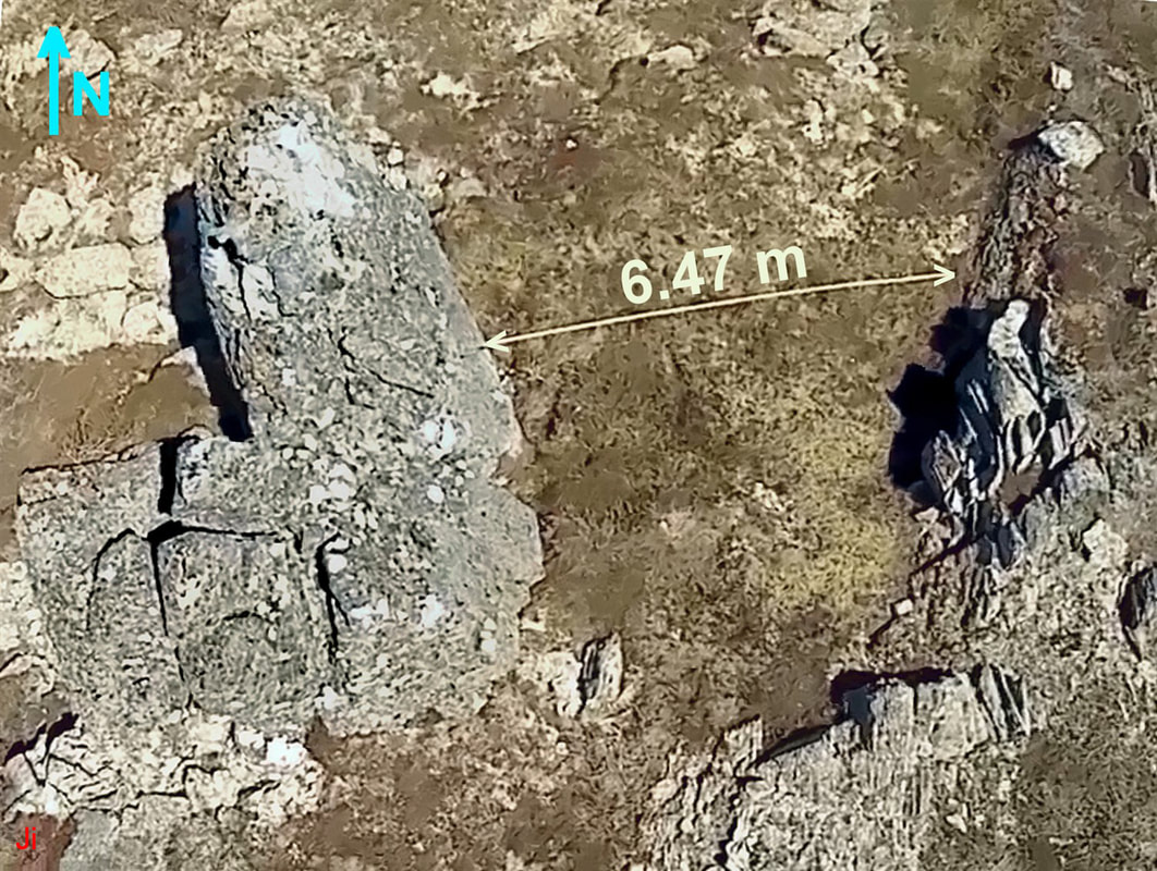
The yellow line seen between the arrows in the above photo is a tape measure laid on the ground. The tape measure links two rock faces that might have been in contact before the blocks seen on the left were glacially displaced.
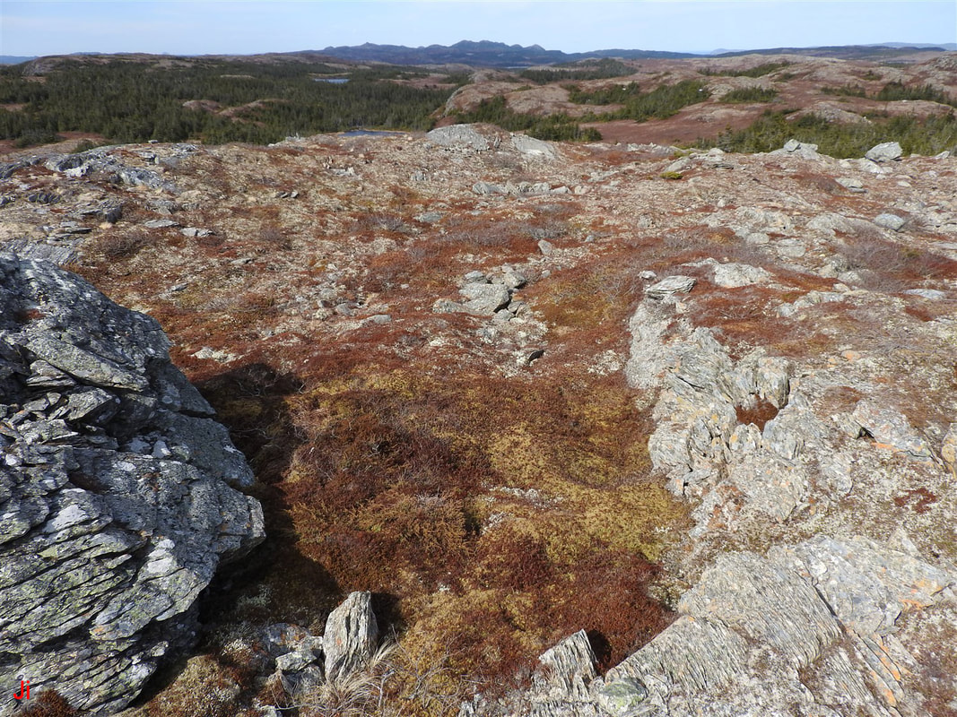
A view of the gap adjacent to the group of blocks, IF-09, is shown above. The rock on the right is bedrock, some of which has been strongly disrupted by ice. The ground in the central area is filled with rock debris, peat and vegetation.
Another view of the gap between the blocks, IF-09, and adjacent exposed bedrock is shown above. The snow patch is roughly level and sits in the lowest portion of the gap. The area occupied by the snow approximately marks the original location of the bedrock outcrop that was glacially shifted to form IF-09.
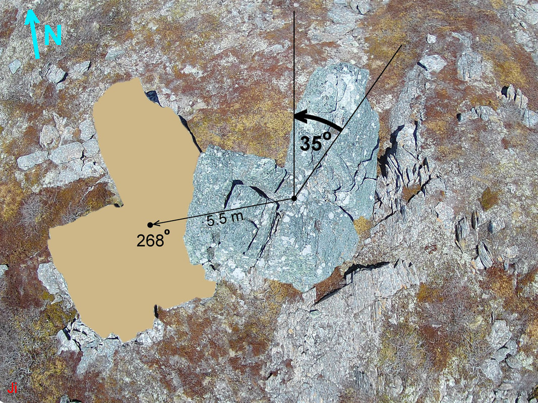
The lateral displacement of IF-09 is illustrated in the above diagram. On average, the blocks were shifted westward by about 6.5 m. Part of this shift was achieved via a rotation of approximately a right angle about a horizontal axis. The rest of the shift (~5.5 m) was a lateral displacement. It is unclear whether the blocks first rotated about a horizontal axis in response to ice loading, and then were translated down-ice, or whether the lateral translation occurred first, followed by the blocks settling into their present rotated orientation. In addition to horizontal translation, the blocks appear to have undergone a 35 degree rotation about a vertical axis.
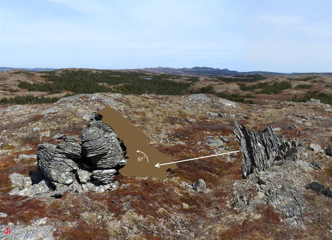
The two surfaces shaded with cyan on the above photo represent failure surfaces following a major cross joint originally present in the foliated bedrock. It appears plausible that the blocks comprising IF-09 separated from bedrock, at least partially, along the indicated failure surfaces. The angles marked on the diagram show the slopes of two rock surfaces that were potentially in contact before the blocks, IF-09, were shifted. Summing the two indicated angles yields the angle of rotation of IF-09 about a horizontal axis, approximately 97 degrees. This angle of rotation agrees with the observation that the foliation in host bedrock dips vertically, whereas the foliation in IF-09 has a near zero angle of dip.
The rotation and translation of part of the group of blocks, IF-09, is shown in the above diagram. The diagram was constructed to hint at the possible placement of some of the blocks before glacial displacement occurred. The precursor to IF-09 was likely a protruding bedrock feature, thereby exposed to enhanced loading by glacial ice. However, the feature appears to have survived loading by warm-based glaciers sliding on bedrock, before finally yielding under the combined effects of frost heave and shear stress imparted by cold glacial ice deforming in creep. The layout of blocks in IF-09 is complex, with only the blocks on the east side of the feature (right side in above photos) showing determinable linkages back to bedrock.
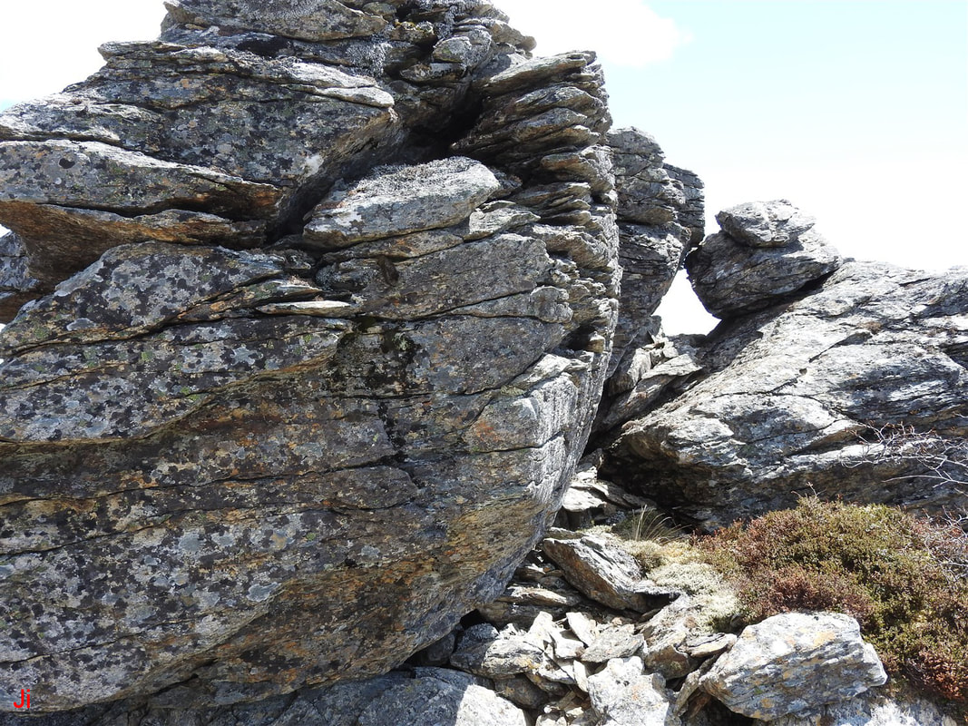
A view of the north end (camera looking south) of IF-09 is shown above. Note the curvature visible on the rock on the west (right as seen in photo) side of the block. This curved side surface was a former top surface. The rounding indicates erosion by temperate glacial ice moving in basal-sliding mode. Note the large block lying in the right-hand background and extending off the right edge of the above frame. This block also possesses a glacially smoothed surface as seen in the following photo.
The presence of smoothed and rounded side surfaces on the blocks comprising IF-09 supports the interpretation that these blocks were rotated approximately 90 degrees about a horizontal axis by ice loading following an extended episode of basal-slip glacial erosion.
Labeling the Individual Components of IF-09
The photos below assign labels to the major blocks comprising IF-09. These labels will be used throughout the remainder of this section.
The photos below assign labels to the major blocks comprising IF-09. These labels will be used throughout the remainder of this section.
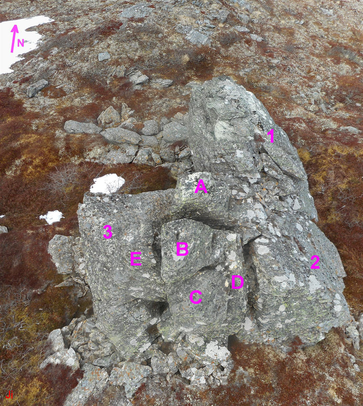
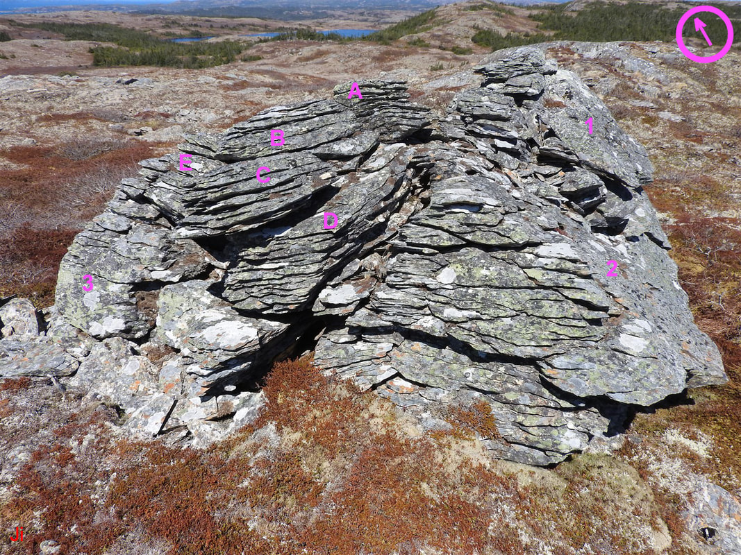
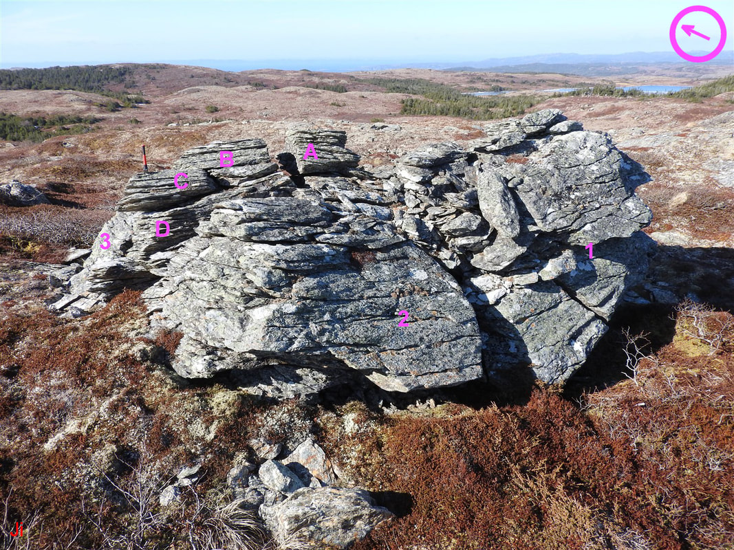
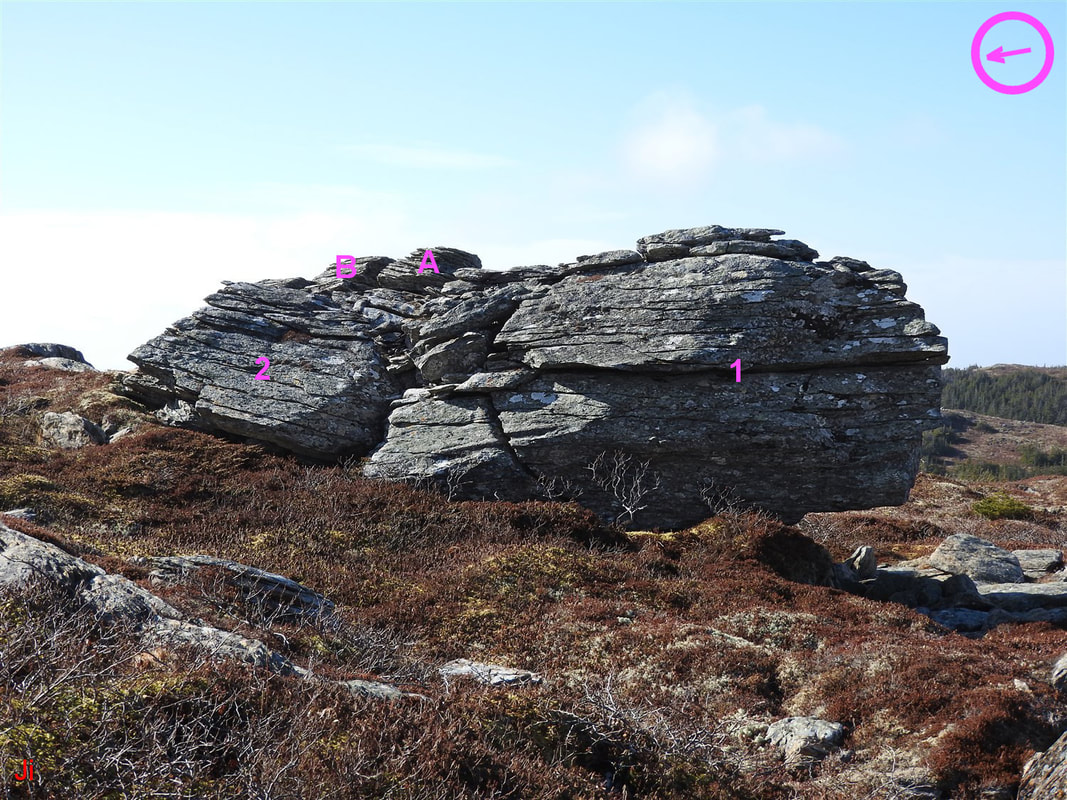
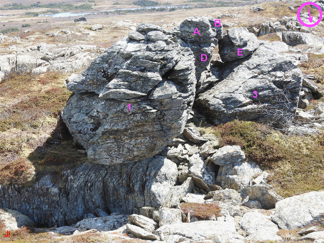
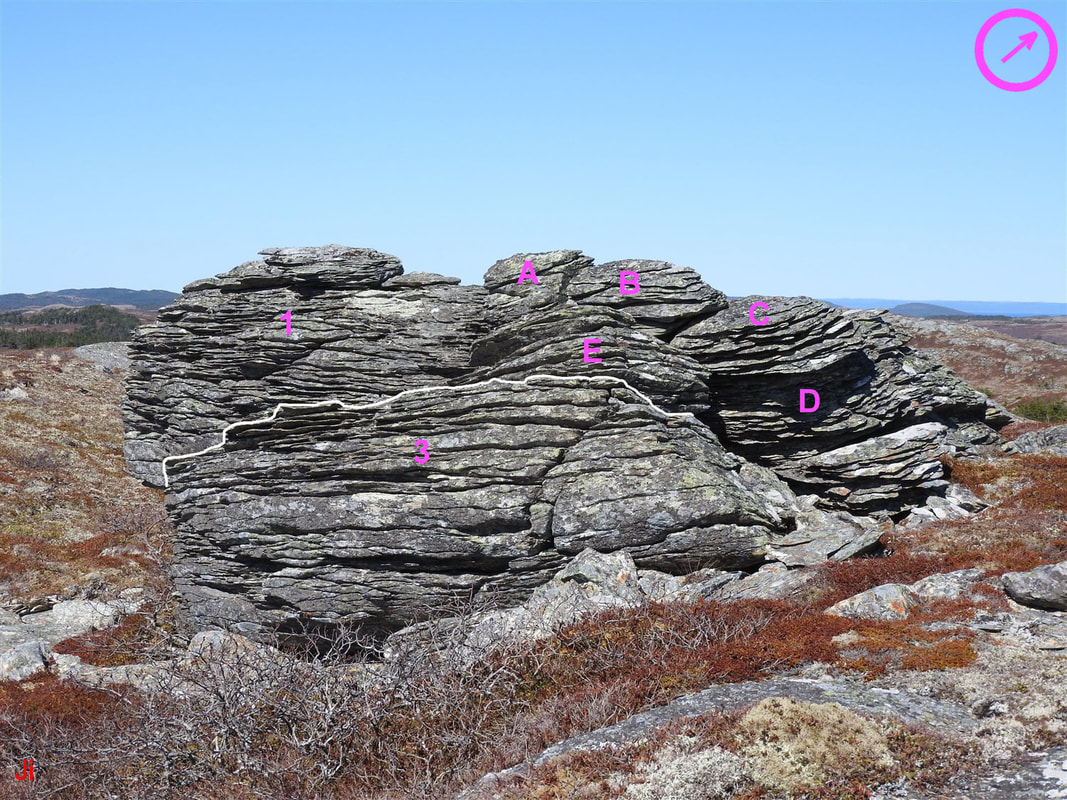
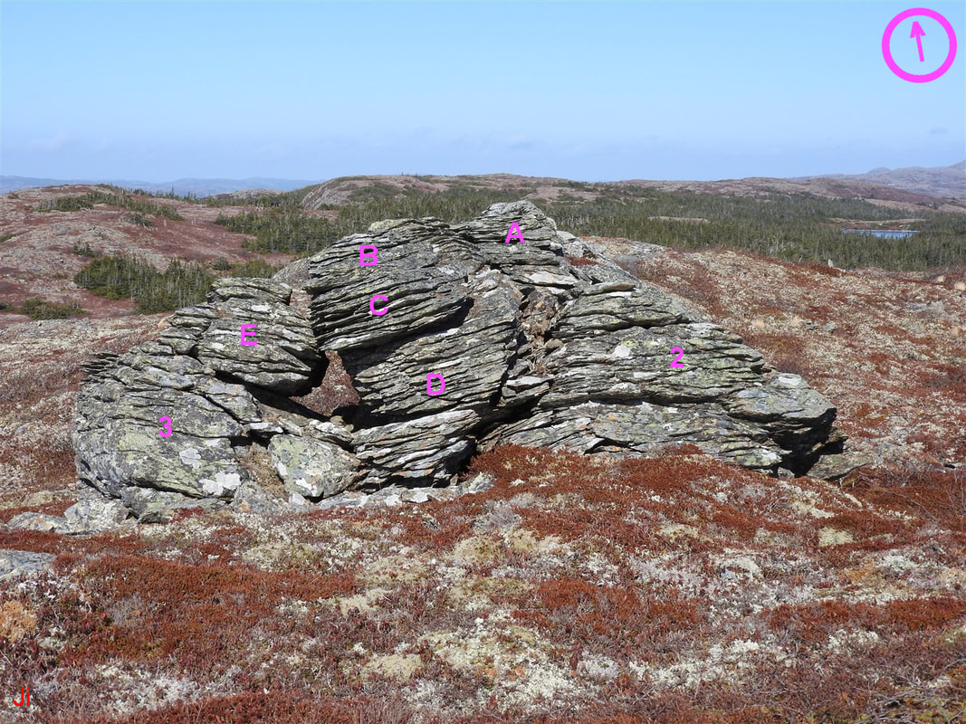
The arrows appearing in the upper right corners of the above photos indicate the compass direction in which the camera was pointing. The second-to-last photo above includes a white line sketched in to delineate the low-contrast boundary between block 3 and the background blocks. Blocks 1, 2 and 3 are the three largest blocks in the assembly. Blocks 1 and 2 show surfaces (now facing east) that separated directly from adjacent bedrock following failure on a major cross joint. Block 3 shows a former top surface (now facing west) that was subjected to basal slip glacial erosion (see "Description and Layout of IF-09" above). The blocks given letter designations (A through E) are smaller blocks that have undergone more complex displacements than the larger (numbered) blocks. Some of the letter-designated blocks might be upside-down (relative to blocks 1, 2 and 3) or turned around backwards. Blocks 1, 2 and 3 contain faults that separate these large blocks into multiple components. Displacements on the faults are small enough that the individual rock sections are clearly recognizable as having been originally joined.
Analysis of Erosion Patterns
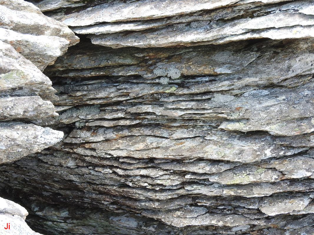
The surfaces of the blocks comprising IF-09 show variable patterns of erosion, the erosion primarily taking the form of grooves following foliation in the rock. The grooves vary in depth and frequency depending on the location and orientation of various rock surfaces. It is important to note that either the erosion patterns observed on the rock surfaces developed within the last 11000 years (Holocene erosion), or else that the erosion patterns developed in a subglacial environment.
If erosion patterns developed within the last 11000 years, then an explanation for their variability is needed. There is no clear evidence of lack of homogeneity in the host rock. Bedding planes in the sedimentary rock are barely discernible and the pronounced foliation in the rock is of tectonic origin. The foliation seems to permeate the rock of IF-09 uniformly and similar foliation appears to affect all surrounding bedrock within a radius of hundreds of meters.
Given that the rock comprising IF-09 is taken to be roughly homogeneous, then the next consideration becomes whether or not the rock is isotropic. Clearly the foliation represents a significant anisotropy. However, the rock appears largely isotropic when consideration is restricted to a plane parallel to the foliation, that is, parallel to the ground at the present orientation of the blocks comprising IF-09. The rock, at its present orientation, would be expected to show approximate cylindrical symmetry in its characteristics about a vertical axis given that foliation comprises the sole source of anisotropy. The condition of homogeneity would further imply that there should be little variation in the intrinsic characteristics of the rock at different heights above the ground.
The analysis of erosion patterns will begin with a look at spatial variations in erosion patterns near the area where blocks C and D make contact.
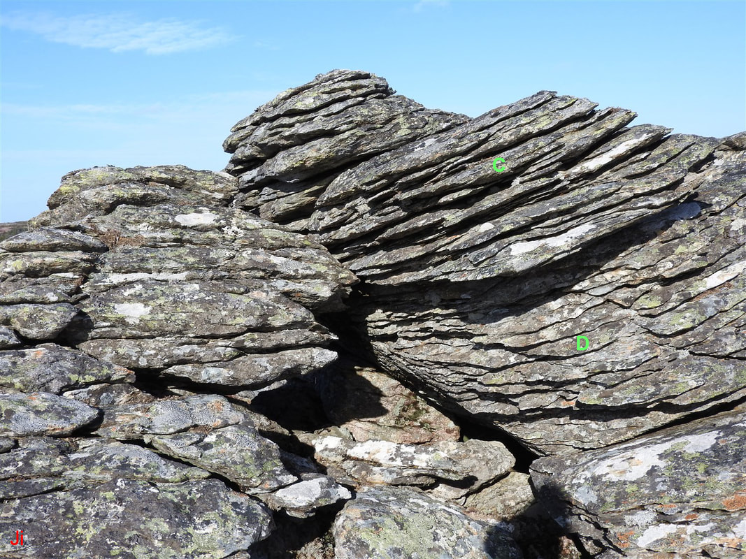
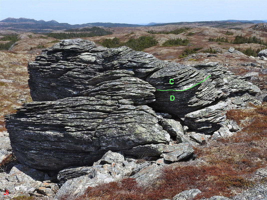
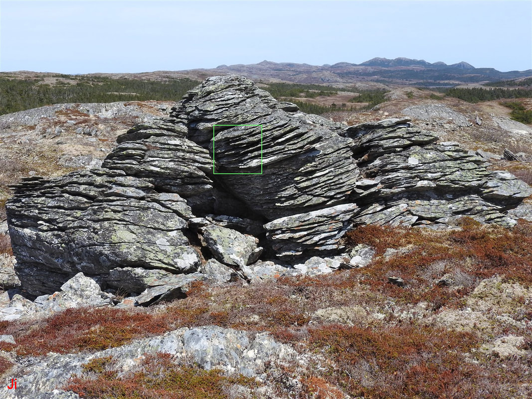
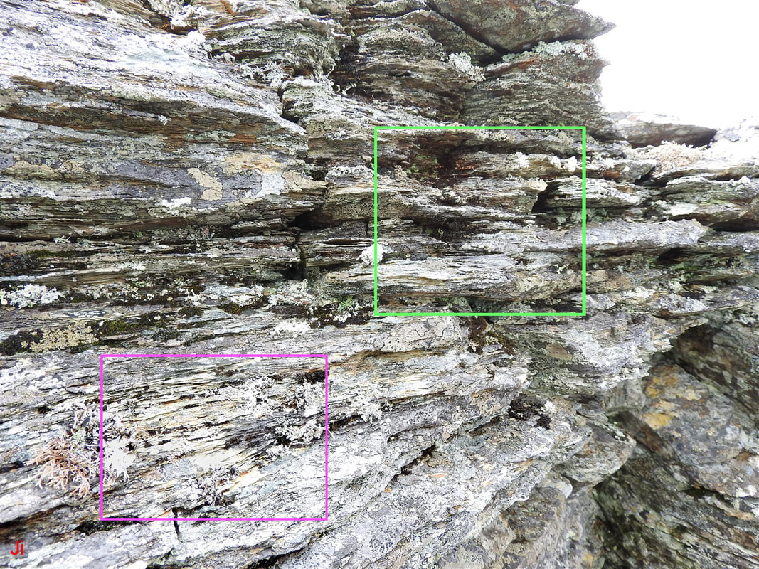
The two photos above show blocks C and D lying in contact on the south end of the assembly of blocks, IF-09. Inspection of the contact between the blocks indicated that the contact is not simply a fault and that block C settled on top of block D by chance. There was no clear indication that either block C or block D underwent significant rotation (about either a horizontal or vertical axis) relative to the main blocks, 1, 2 and 3. Both blocks C and D show pronounced grooved erosion on surfaces facing generally southwest.
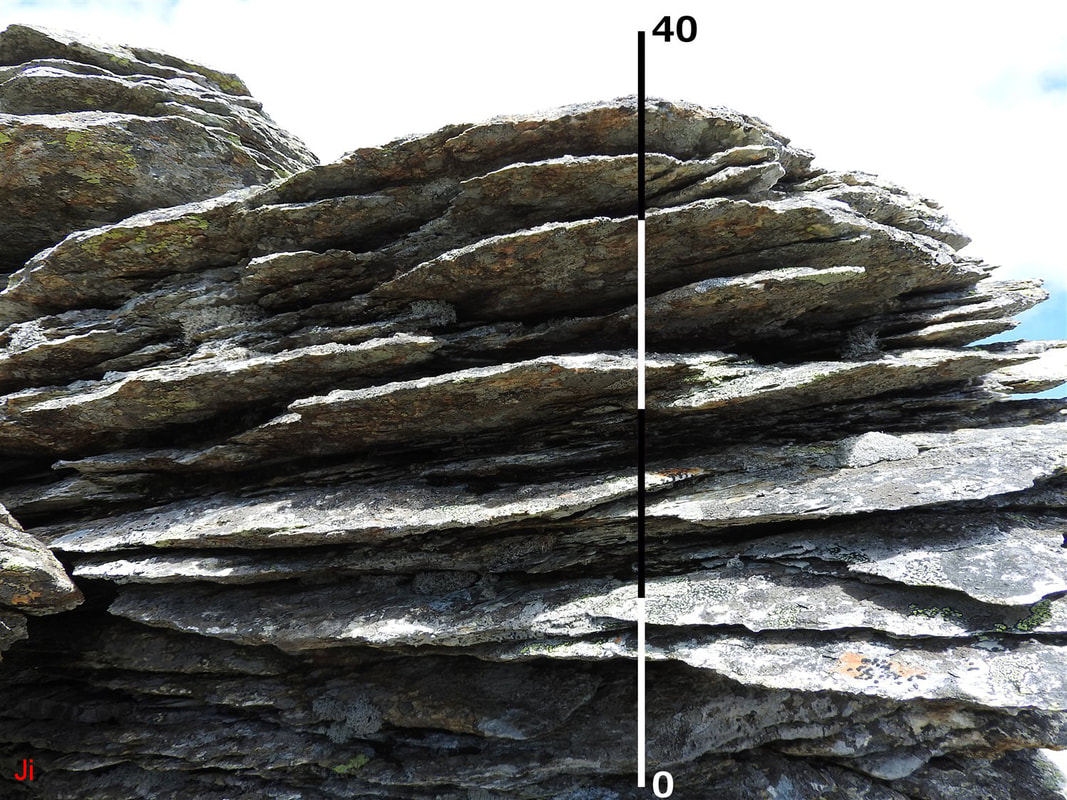
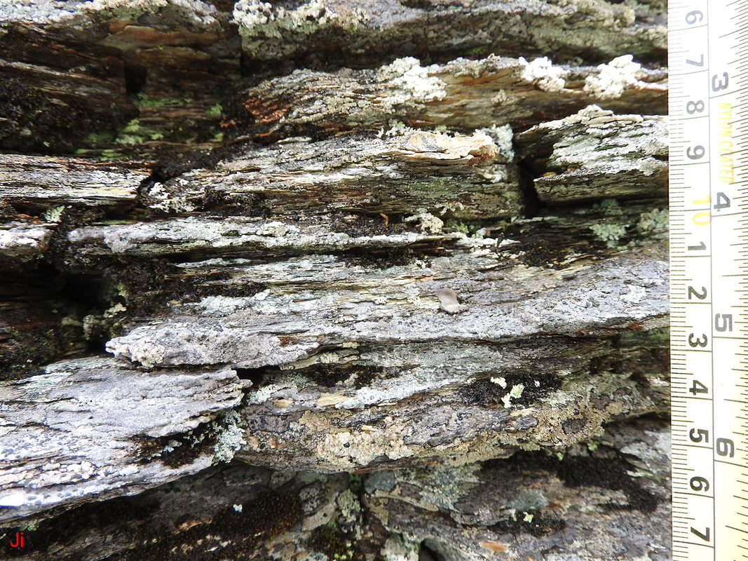
The pronounced grooved erosion of the southwest-facing surface of block C is shown above. The scale is in centimeters. The area framed in the above photo is shown below (green box in photo).
The following two photos indicate the depth of the erosion grooves on the southwest corner of block C.
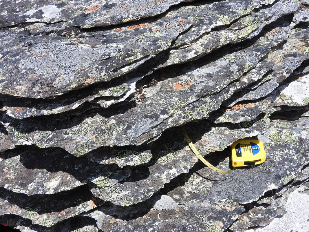
The tape measure seen in the preceding photo reaches to the bottom of a groove and reads 18 cm at the point where it crosses the edge of the rock.
The above photo shows the northeast-facing surface of block C. This surface, 180 degrees opposite to the highly grooved surface shown in the previous photos of block C appears to be a failure surface where block C separated from bedrock or from another block. Block C was tested with a pry bar to determine whether or not the block was intact. There was no indication that any of the joints seen in the block extended across the entire block.
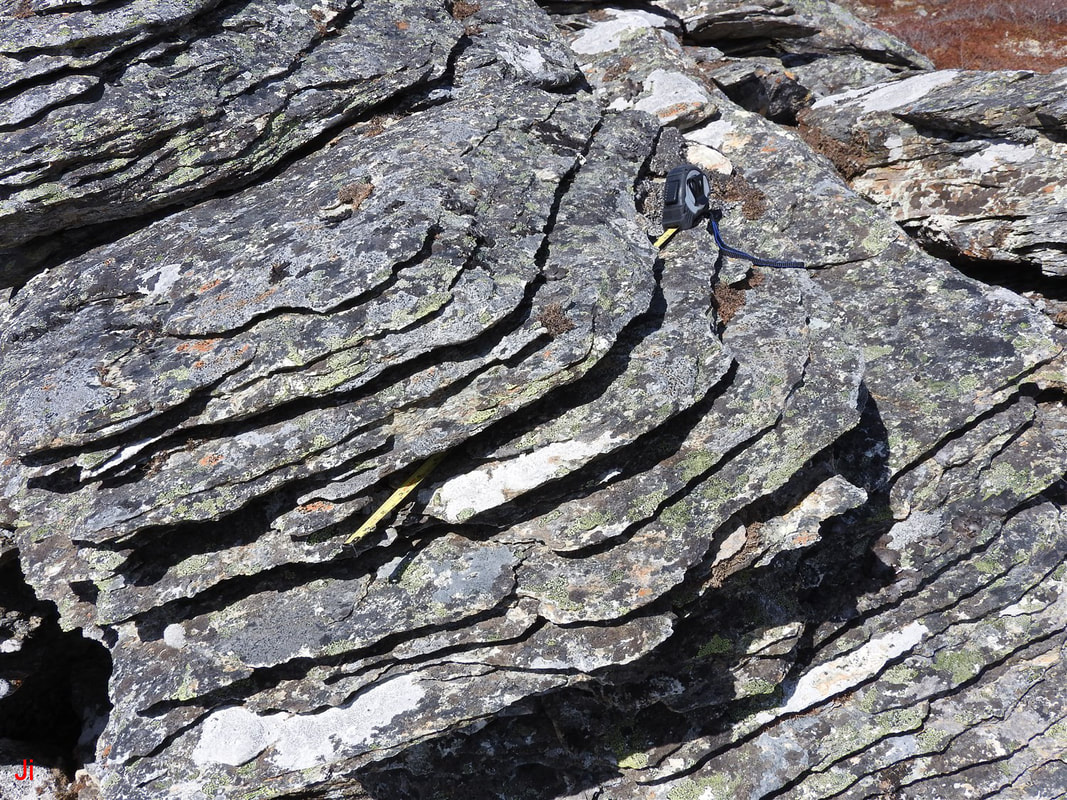
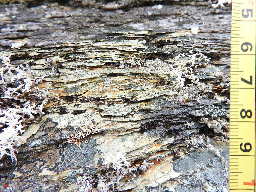
The above photo shows the southwest-facing side of block D. The eroded surface demonstrates a grooved pattern, similar to block C, but the grooves are shallower and more closely spaced on block D than on block C.
The above two photos show block C overlying block D. The difference in the coarseness of the erosion grooves on the two blocks is evident in the photos.
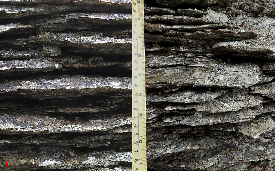
The photo on the left above shows the erosion pattern on block C, just above the contact between blocks C and D, while the photo on the right shows the eroded surface of block D just below the contact. The erosion patterns on both blocks shows a periodic character and a difference in both the period and the depth of the grooved pattern is apparent when directly comparing the two sections. Measurement of the depth of the grooves near the contact indicated a transition in groove depth from about 11 cm average depth (block C) to 5 cm average depth (block D).
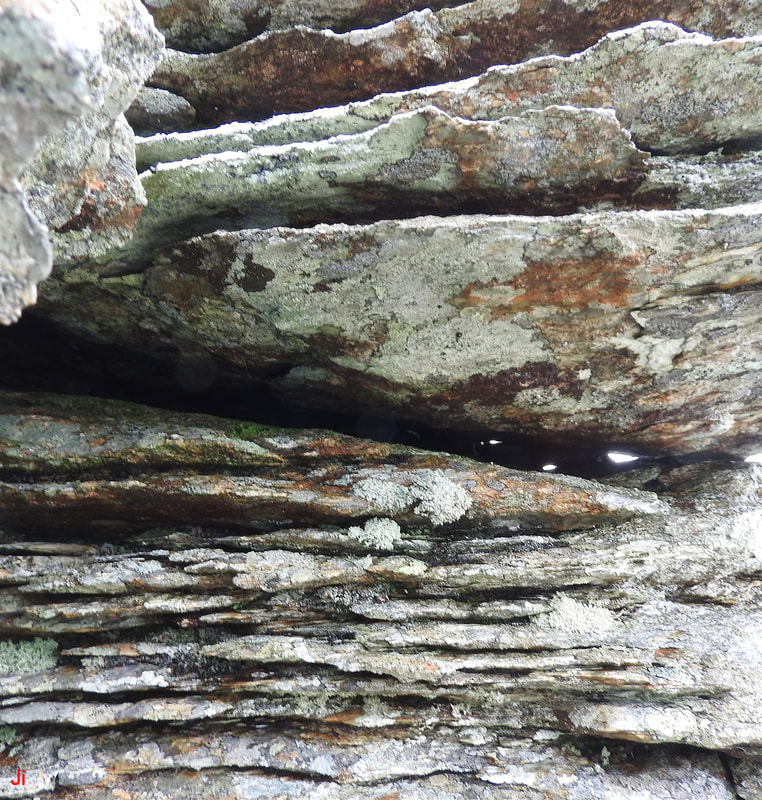
A closeup of the contact between block C and block D is shown above. The boundary appears as a dark gap running across the center of the photo at a slanted angle. Bright patches of light shining through from the opposite side of the blocks can be seen on the right-hand side of the boundary gap.
In conclusion, observations of an abrupt change in the grooved erosion pattern visible upon crossing the boundary between block C and block D leads to the interpretation that the observed erosion occurred before the blocks occupied their present abutting locations. Unless the host rock is inhomogeneous and the two blocks differ in composition or texture (not in agreement with observations at this site), there is no reason for the character of the erosion pattern to suddenly change at the boundary. This interpretation pushes the time at which the erosion patterns formed back to the time before the blocks assumed their present positions. The erosion then becomes attributable to a subglacial process.
In conclusion, observations of an abrupt change in the grooved erosion pattern visible upon crossing the boundary between block C and block D leads to the interpretation that the observed erosion occurred before the blocks occupied their present abutting locations. Unless the host rock is inhomogeneous and the two blocks differ in composition or texture (not in agreement with observations at this site), there is no reason for the character of the erosion pattern to suddenly change at the boundary. This interpretation pushes the time at which the erosion patterns formed back to the time before the blocks assumed their present positions. The erosion then becomes attributable to a subglacial process.
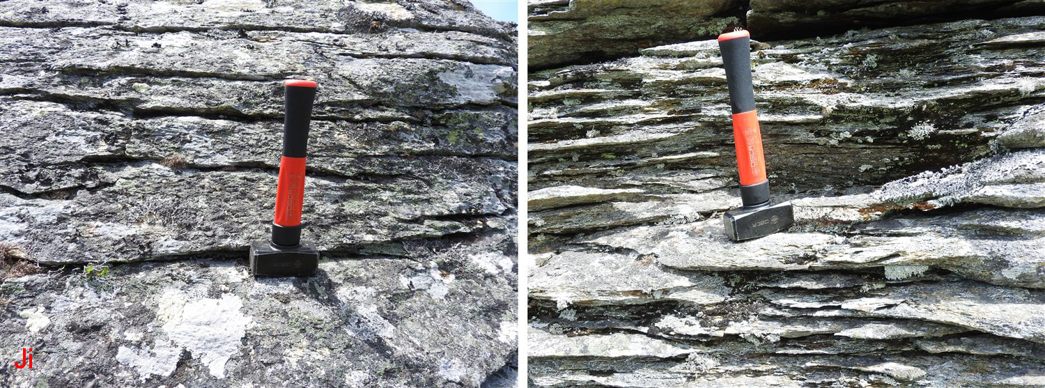
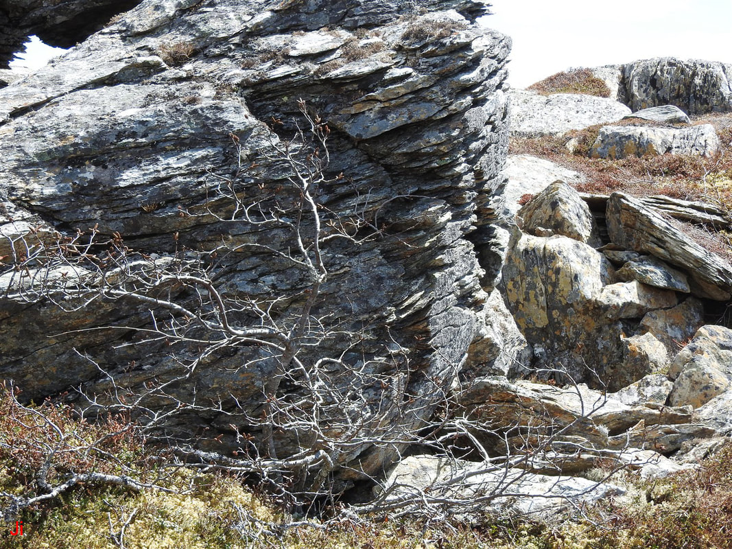
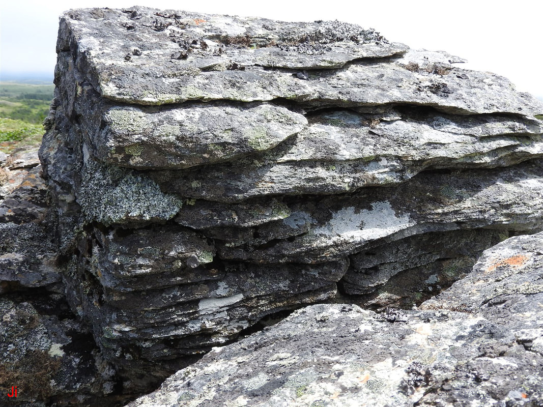
The above photos show opposing sides of block 1. The hammer rests at about the same height above ground in each photo. The photo on the left shows a surface facing eastward, while the right-hand photo shows a west-facing surface. Clearly, the erosion patterns differ on the two sides of the block. The surface seen on the left was interpreted to be a failure surface where block 1 separated from bedrock. The surface on the right is a former top surface, showing initial smoothing by basal slip glacial erosion before having undergone a secondary phase of erosion that generated the densely grooved appearance seen in the photo.
In the remaining discussion of this Illustrative Feature 09, the erosion patterns seen on the various blocks are interpreted as representing instances of erosion by subglacial ice extrusion. Within this interpretation, the feature, IF-09, was subjected to penetration by groundwater/ice while still attached to bedrock. The grooved erosion patterns were formed by ice extrusion occurring beneath a cold-based glacier. A combination of frost heave and loading by cold glacial ice deforming in creep eventually tore the blocks of IF-09 loose from bedrock and transported them a short distance.
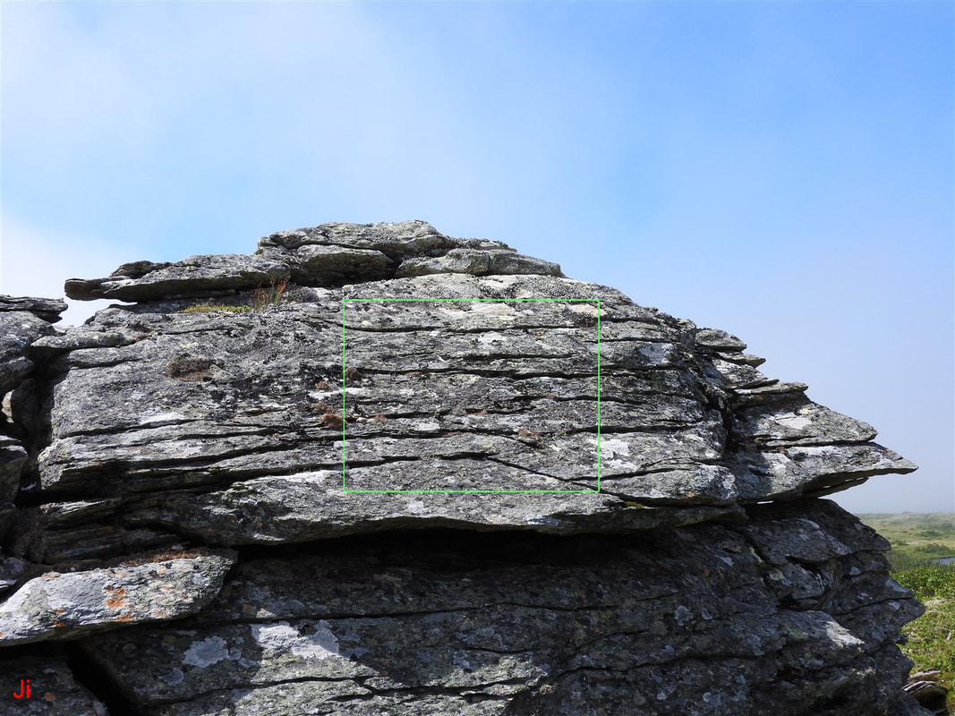
Grooves are seen on both the former bottom and the former top of block 1. The main difference between the erosion of the two opposing surfaces is that the grooves are more closely spaced on the former top side of the block and the top-side grooves tend to be deeper. A question arises as to why there would be any grooves formed by water/ice intrusion on the former bottom side of the block, given that this former bottom surface was attached to adjacent bedrock while the erosion process was ongoing. Water/ice intrusion alone cannot account for the formation of the bottom-side grooves. Rather, it must be assumed that these grooves largely formed after block 1 separated from bedrock. The bottom-side grooves thus seem to represent the result of Holocene erosion. Nevertheless, there is a probable connection between the bottom-side grooves and a subglacial ice segregation process. Generally, the bottom-side grooves appear to transition to joints. The grooves themselves are shallow, of the order of 1-3 cm deep. The first photo below shows the east-facing side of block 1. The second photo below shows a closeup of the area framed by the green rectangle in the first photo.
In the remaining discussion of this Illustrative Feature 09, the erosion patterns seen on the various blocks are interpreted as representing instances of erosion by subglacial ice extrusion. Within this interpretation, the feature, IF-09, was subjected to penetration by groundwater/ice while still attached to bedrock. The grooved erosion patterns were formed by ice extrusion occurring beneath a cold-based glacier. A combination of frost heave and loading by cold glacial ice deforming in creep eventually tore the blocks of IF-09 loose from bedrock and transported them a short distance.
Grooves are seen on both the former bottom and the former top of block 1. The main difference between the erosion of the two opposing surfaces is that the grooves are more closely spaced on the former top side of the block and the top-side grooves tend to be deeper. A question arises as to why there would be any grooves formed by water/ice intrusion on the former bottom side of the block, given that this former bottom surface was attached to adjacent bedrock while the erosion process was ongoing. Water/ice intrusion alone cannot account for the formation of the bottom-side grooves. Rather, it must be assumed that these grooves largely formed after block 1 separated from bedrock. The bottom-side grooves thus seem to represent the result of Holocene erosion. Nevertheless, there is a probable connection between the bottom-side grooves and a subglacial ice segregation process. Generally, the bottom-side grooves appear to transition to joints. The grooves themselves are shallow, of the order of 1-3 cm deep. The first photo below shows the east-facing side of block 1. The second photo below shows a closeup of the area framed by the green rectangle in the first photo.
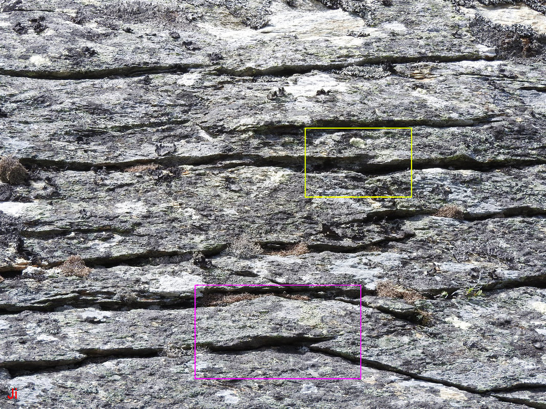
Closeups of grooves eroded into the east-facing (former bottom) side of block 1 are shown in the two photos below. The first photo below shows the area framed by the yellow rectangle above, while the second photo below shows the area framed by the magenta rectangle above.
Both of the photos above illustrate grooves that are shallow (~2 cm deep) and rapidly give way to narrow slots which presumably taper to joints.
A possible explanation for the bottom-side grooves stems from considering how groundwater penetrated the frozen, foliated bedrock. As supercooled pressurized groundwater reached near-surface rock, reduced confinement would result in expansion of pore spaces and segregation of ice within the expanded pore spaces. Acting at the scale of individual phyllosilicate crystal grains, this ice-segregation process would locally damage the integrity of otherwise well-indurated homogeneous rock, making the rock friable and thus more vulnerable to secondary erosion by Holocene processes. If the groundwater moving through frozen bedrock tended to concentrate in channels, then a repeating series of grooves might arise when secondary erosion processes preferentially attacked rock near the channels.
The preferential erosion of rock damaged by micro-scale ice segregation would be expected to occur on all surfaces of a block affected by groundwater penetration and associated ice segregation, not just the surfaces where water entered. The grooves seen on the original top sides of the blocks comprising IF-09 were likely augmented by the same processes of secondary erosion that widened grooves on the former bottom sides of the blocks. The grooves formed on the top-side surfaces would thus reflect two sequential episodes of erosion, the first subglacial (primary erosion by ice extrusion) and the second subaerial (secondary erosion by rainfall and freeze-thaw action).
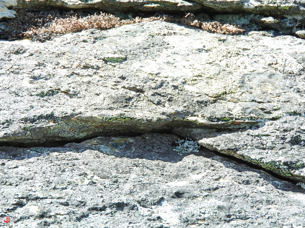
The white rectangle in the above photo highlights an area of the east-facing side of block 1, on the lower third of the block. This area is notable for the lack of distinct grooves such as are seen on many other surfaces of the blocks comprising IF-09. A closeup of the highlighted area is shown below.
The lack of pronounced grooves on the rock surface pictured above contrasts sharply with other more severely eroded areas of If-09. Several explanations might account for variations in the amount of erosion.
If pressurized groundwater from depth was reaching the site of IF-09 by moving in faults or cross joints, then regions of rock near these conduits might experience significant groundwater-driven erosion while nearby areas remained less affected.
Alternatively, those areas showing less evidence of groundwater-driven erosion might be areas where confinement of rock by adjacent rock was greater. The stronger confinement would limit widening of joints and thereby inhibit ice segregation.
Variations in glacial ice pressure caused by movement of ice past bedrock obstructions could favor groundwater/ice flow through particular sections of bedrock. Rock surfaces where pore water/ice was entering rock would tend to erode less than surfaces where ice was exiting.
A view of the west side of block 1 is shown above. This view shows the former top surface of the block before the block was rotated by glacial action. Eroded grooves are largely absent from the lower third of the west side of block 1, mirroring the absence of eroded grooves on the lower third of the east side of block 1. The relative lack of grooved erosion features on both sides of the lower third of block 1 could be interpreted as indicating that pore water migration and ice segregation were significantly reduced in the lower third of block 1 as compared with the upper two thirds of block 1.
In summarizing the causes of erosion on block 1, it can be postulated that the east-facing upper two thirds of the block shows grooves formed by pore water entry channels, the west-facing upper two thirds of the block shows grooves formed by ice exiting the rock and the lack of grooves on the bottom third of the block indicates a reduced degree of penetration by pore water or segregated ice.
In summarizing the causes of erosion on block 1, it can be postulated that the east-facing upper two thirds of the block shows grooves formed by pore water entry channels, the west-facing upper two thirds of the block shows grooves formed by ice exiting the rock and the lack of grooves on the bottom third of the block indicates a reduced degree of penetration by pore water or segregated ice.
The above photo shows the north end of block 1. Joints (widened by erosion enough to make them visible) can be seen traversing the entire thickness of the block. These visibly widened joints appear to indicate channels for groundwater/ice moving through the rock. The north-end surface of the block is a failure surface following a cross joint aligned parallel to the direction of groundwater movement. Accordingly, groundwater would not tend to enter or exit the block along paths normal to the north-end surface.
A closeup of widened joints intersecting the north-end surface of block 1 is shown above. The two joints visible near the middle of the frame extend across the full width of block 1. This raises the question as to why the block did not fail on these joints when the block was being torn from bedrock by glacial ice loading. Note that the block has failed on another joint running parallel to the above-pictured joints (see photo directly preceding the above photo).
The fact that the above-pictured joints survived presumably large amounts of irregular stress without yielding suggests that the joints are incomplete. That is, the joints do not traverse the full extent of the block. This characteristic appears to be a common feature of joints that are formed as groundwater/ice channels. Joints that appear wide in some places, irregular but trending along foliation, are seen abundantly in frost-heaved and ice-disrupted rock on the Avalon Peninsula. These widened characteristic joints often peter out, giving a false illusion of plasticity in rock that is clearly brittle. Loose blocks with sub-meter dimensions can possess extensive joints widened to several millimeters in some places, these joints tapering to zero width (vanishing) elsewhere and thus not compromising the mechanical integrity of the overall block. Observations suggest that incomplete widened joints in ice-disrupted bedrock can reasonably be interpreted as an indicator of groundwater/ice paths through the rock.
The fact that the above-pictured joints survived presumably large amounts of irregular stress without yielding suggests that the joints are incomplete. That is, the joints do not traverse the full extent of the block. This characteristic appears to be a common feature of joints that are formed as groundwater/ice channels. Joints that appear wide in some places, irregular but trending along foliation, are seen abundantly in frost-heaved and ice-disrupted rock on the Avalon Peninsula. These widened characteristic joints often peter out, giving a false illusion of plasticity in rock that is clearly brittle. Loose blocks with sub-meter dimensions can possess extensive joints widened to several millimeters in some places, these joints tapering to zero width (vanishing) elsewhere and thus not compromising the mechanical integrity of the overall block. Observations suggest that incomplete widened joints in ice-disrupted bedrock can reasonably be interpreted as an indicator of groundwater/ice paths through the rock.
Grooved Erosion Patterns Formed by Ice Extrusion: Scale Independence
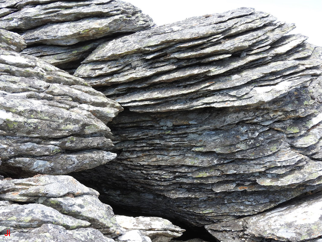
Subglacial ice extrusion can generate a grooved erosion pattern aligned with the foliation in affected bedrock. This erosion pattern demonstrates a degree of scale independence extending from sub-millimeter periodicity to periodicity of the order of tens of centimeters.
Subglacial ice extrusion can generate a grooved erosion pattern aligned with the foliation in affected bedrock. This erosion pattern demonstrates a degree of scale independence extending from sub-millimeter periodicity to periodicity of the order of tens of centimeters.
A view of the west-facing side of block 1 is shown above. The area enclosed by the large white rectangle is shown below on the left. The area enclosed by the small magenta rectangle is shown below on the right.
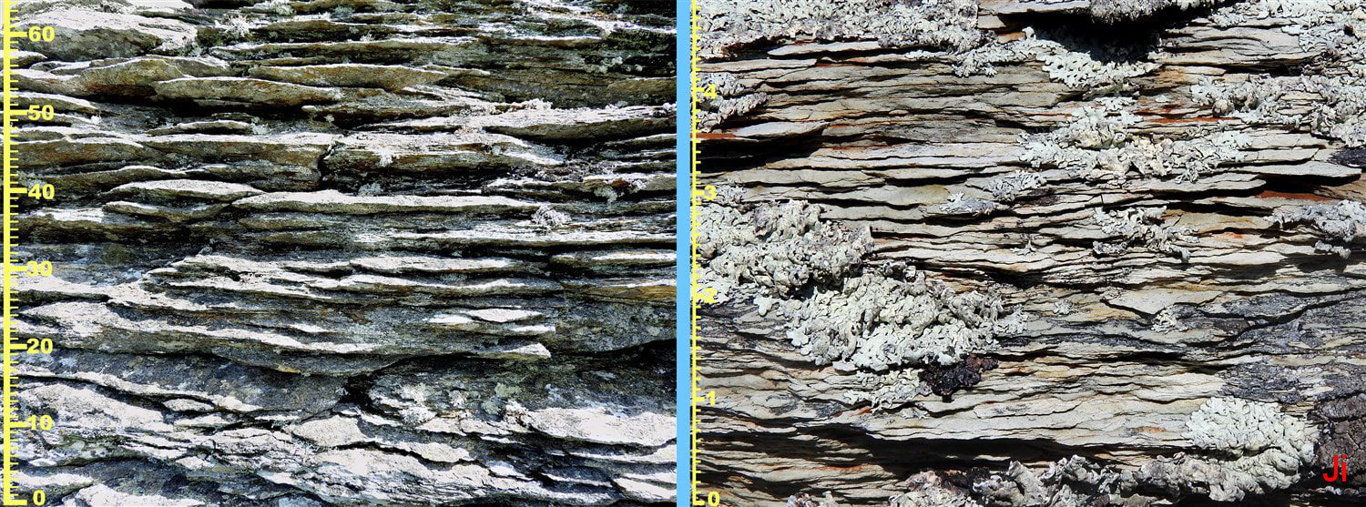
The two grooved erosion patterns pictured above show similar form. The scale indicators, marked in yellow, read centimeters. The erosion features pictured on the left are about 15 times larger than those appearing on the right. Both erosion features were presumed to be generated in a cold subglacial environment by ice that was extruded from bedrock. Observations of grooved bedrock erosion features at other locations on the Avalon Peninsula suggest that the coarser grooved erosion feature reflects a higher rate of ice extrusion than does the more finely grooved feature. This qualitative explanation for the difference between the two features was inferred from observed positive correlations between coarser grooved erosion features and more severe local bedrock disruption.
The above photo shows an area, framed in a green rectangle, of a grooved erosion pattern on the west side of block 1. The photo below provides a closeup of the area delineated by the above rectangle.
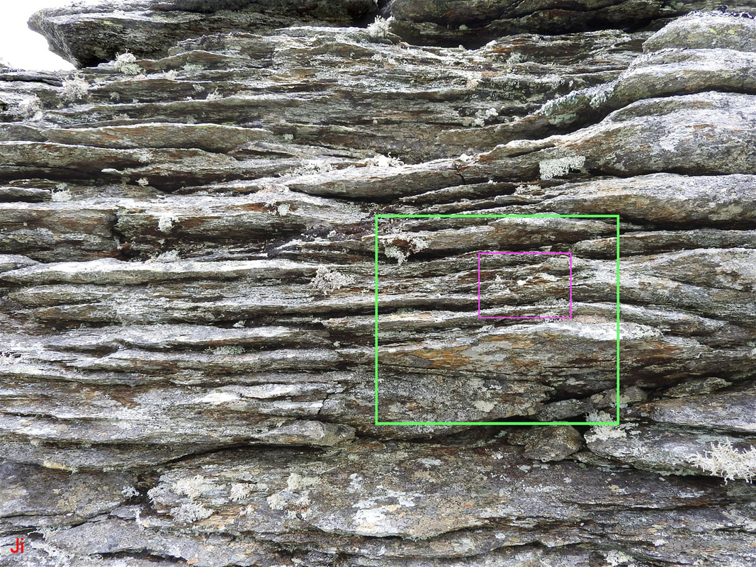
The following two photos show, first, a zoomed-in view of the area enclosed in the outer green rectangle above, and second, a further zoomed-in view of the area enclosed in the inner magenta rectangle above.
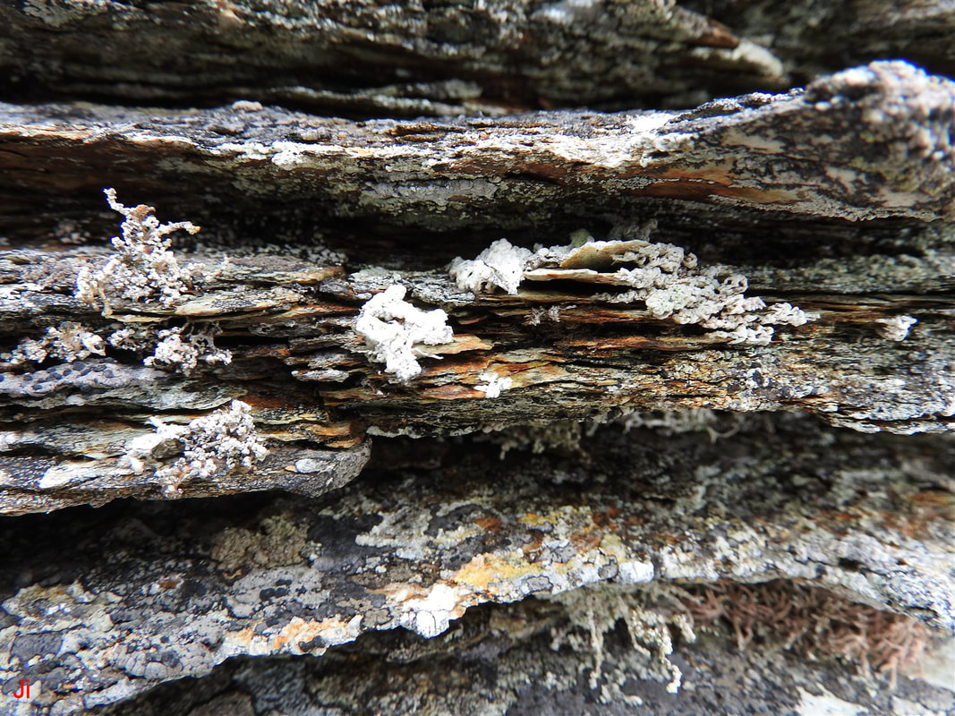
The above photo illustrates a smaller-scale grooved erosion pattern (center of photo) formed within a larger-scale grooved erosion pattern. The smaller-scale pattern might be wrongly taken as indicating that the rock is intrinsically vulnerable to delamination and possesses a flaky texture similar to a soft macro-crystalline phyllosilicate mineral (like muscovite). However, the illustrated delamination is an artifact of the penetration of the rock by super-cooled pore water and segregated ice. Although the rock is composed mainly of phyllosilicate mineral grains, the grains are small and interlinked between layers in a manner that makes the rock strongly resistant to cleavage by external mechanical stress. It appears as though internal stress generated by ice-crystal growth pressure between phyllosilicate crystal grains is the key process responsible for delaminating the rock and yielding the flaky, friable texture shown above.
Some further examples of finely delaminated rock from the west-facing sides (former top sides) of blocks comprising IF-09 are shown below. There is little evidence of significant fine-scale delamination of rock on the east-facing sides (former bottom sides) of the blocks comprising IF-09.
Some further examples of finely delaminated rock from the west-facing sides (former top sides) of blocks comprising IF-09 are shown below. There is little evidence of significant fine-scale delamination of rock on the east-facing sides (former bottom sides) of the blocks comprising IF-09.
|
|
The second (right) photo above is a closeup of the area on the west side of block 1 enclosed by the blue rectangle drawn in the first (left) photo above.
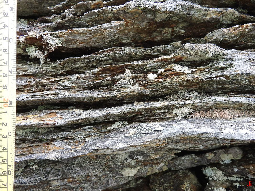
The first of the two photos shown above corresponds to the upper (green) rectangle in the previous locator photo, while the second of the above photos corresponds to the lower (magenta) rectangle in the locator photo. Delamination of the rock at the sub-millimeter scale is evident in the closeup photos. Rocks of similar composition at locations near IF-09 show no evidence of fine-scale delamination, nor can they be readily delaminated by hammering them or crushing them UNLESS the rocks occur in an area showing independent evidence of past disruption by ice wedging.
The delamination of rock at the sub-millimeter scale by pore water penetration and ice segregation implies that pore water is migrating everywhere throughout the rock. Observations of repeating grooves or channels that are spaced centimeters or tens of centimeters apart implies that groundwater movement through the rock tends to concentrate along certain channels. The co-existence of fine-scale and coarse-scale layered erosion features implies that both the smaller-scale and larger-scale processes are operating simultaneously. That is, pore water migration tends to concentrate in channels, but penetration of pore water and segregation of ice occurs not just in the channels but throughout the rock. The distribution of pore water paths appears intrinsically nonuniform and it seems to show a significant spatial periodicity. A positive feedback loop (instability) whereby pore water migration and accompanying ice segregation would render rock more vulnerable to pore water penetration could account for the nonuniformity.
In summary, the grooved erosion patterns described above show an element of periodicity that is self-similar over at least two orders of magnitude in linear dimensions. This suggests that similar processes are responsible for generating grooves in the rock at the 10 centimeter scale and at the sub-millimeter scale. The basic processes are described in Bedrock Erosion by Subglacial Ice Extrusion - Part 01.
Additional examples of erosion patterns on the surfaces of IF-09:
Water/ice entry grooves, blocks 1 & 2
Water/ice entry grooves, blocks 1 & 2
The above photo shows the east-facing (former bottom) failure surface of block 2 (sunlit area) along with an orthogonal surface of rock failure where block 2 separated from block 1 (shaded area). Channeled groundwater and associated segregated ice apparently entered the block from the left (direction as seen in photo) and traveled along pathways indicated by the grooves appearing on the shadowed surface. The grooves have subsequently been widened by Holocene erosion exploiting weakness in the rock caused by segregation of ice in spaces between crystal grains.
The tape measure seen in the above photo extends into a groove presumably formed by groundwater intrusion at the original bottom (now east-facing) surface of block 2. The groove is V-shaped to a measured depth of 3 cm and then continues onward into the block with a sub-millimeter thickness.
(To help clarify the discussion in the following two paragraphs, italics are used for compass directions referring to pre-Holocene block orientations and bold letters are used for present-day compass directions.)
The hammer seen in the above photo rests on the east-facing (former bottom) surface of block 2. Three components (separated by faults) comprising the major portion of block 1 are seen to the right. The grooves (water/ice entry grooves, see discussion above) visible in the photo are more densely spaced on the present-day tops of the blocks than on the present-day bottoms. If closer spacing of adjacent entry grooves is presumed to correlate with a higher groundwater intrusion rate, then more groundwater was entering the original (before glacial displacement) east side of the bedrock outcrop (precursor to IF-09) than was entering the original west side. This deduction conforms with other observations of presumed ice-exit groves on the present-day west sides of the blocks comprising IF-09. The ice-exit grooves near the tops of the west-facing sides of the blocks are more numerous and pronounced than the grooves near the present-day bottoms of the blocks.
An excess of groundwater flow and the associated formation of segregated ice along the east side (before glacial shift) of the bedrock outcrop (precursor to IF-09) would be consistent with the east side of the precursor outcrop being lifted relative to the west side. Such differential rates of frost heave would help to account for the observed rotation of the assembly of blocks by 90 degrees about a horizontal axis.
Large ice exit grooves, block 1
The above photo shows a view of the west side of block 1, looking northeast. Many of the grooves seen in the illustrated rock face are more than 10 cm deep.
|
|
The two photos above illustrate deep and coarse grooves at the top of block 1, west side. The overhanging rounded disk of rock (about 20 cm wide) is a remnant of a groove formed by ice extrusion where layers of surrounding rock detached and were carried away by the extruding ice. An overhead view of this protruding feature is shown below.
The top of block 1, west side, looking north, is shown above. The rounded, overhanging section of rock that was highlighted in the two preceding photos can be seen near the left side of the above frame. The top surface of the overhang is flat and flush with adjacent rock. The flat failure surface is a former joint, paralleling foliation. The joint was presumably created and widened by ice segregation as part of an overall subglacial ice extrusion process leading to delamination of the rock.
Large grooves in the northwest corner of block 1 can be seen in the above photo, taken looking southeast. Note that all of the grooves widen toward the west, the original top of block 1.
Large ice exit grooves, block 3
|
|
The yellow dot in the first (left) photo above indicates the location of measurement (second, right photo above) of the depth of a groove formed by extruded ice exiting at the original top (now west-facing) surface of block 3. The measured depth of the groove is 17 cm. At a depth greater than 17 cm, the groove continues inward, but with a thickness of less than 5 mm. Note the irregular fault running just south of the location of the depth measurement and traversing block 3 from top to bottom. Presumably this fault resulted from failure of the rock under stress from glacial loading. However, block 3 shows no evidence of rock failure along any plane parallel to the foliation. This implies that the grooves and associated groundwater/ice channels leading to the grooves do not form complete planes of weakness extending across the entire span of block 3. This incompleteness of the eroded channels formed by groundwater penetration and ice segregation is an identifying characteristic of the eroded channels.
The above photo shows the south end of block 3, looking northeast. An area of intensely grooved rock can be seen on the top, northwest corner of block 3. This area contrasts sharply with the rock surface seen in the foreground, on the bottom southwest corner of block 3. The contrasting erosion patterns presumably represent spatial variations in the rate of ice extrusion from the original top (present-day west) surface of block 3.
|
|
The two photos above show the grooved erosion pattern on the upper northwest corner of block 3. The illustrated eroded surface was an original top (upward-facing) bedrock surface, before block 3 was shifted and reoriented by frost-heave action and glacial action. The erosion pattern may have been amplified during the Holocene. However, it can reasonably be deduced that the pattern originated in a pre-Holocene subglacial environment. Unless block 3 possesses an unrecognized lack of homogeneity in composition or texture, it is unlikely that a distinctive erosion pattern like that shown above would arise during the Holocene, while other nearby and comparably exposed surfaces experienced little or no erosion. Following the analyses presented in this section (Illustrative Feature 09) and in Erosion by Ice Extrusion - Part 01, it can be concluded that the large-groove erosion patterns in blocks 1 and 3 described above were all generated by ice extruded from bedrock in a cold subglacial environment.
Asymmetric erosion, blocks A and B
Block A is shown above, viewed from the north. Channels (widened joints) traversing the block are clearly visible on the north surface. These channels are not accompanied by V-shaped grooves indenting the generally flat north-facing surface of the block. The north-facing surface of block A is neither an entry surface nor an exit surface for groundwater/ice penetrating the rock. The plane of the north-facing surface presumably ran parallel to the direction of groundwater migration.
A test was performed to check whether or not block A was intact. It was not possible to separate layers of the block by prying the layers apart and there was thus no indication that the block was not all one piece.
A test was performed to check whether or not block A was intact. It was not possible to separate layers of the block by prying the layers apart and there was thus no indication that the block was not all one piece.
|
|
The south-facing surface of block A is shown in the two photos above. The second (right) photo is a detail of the first (left) photo. As with the north-facing surface of block A, there is evidence of water/ice channels traversing the block, but the channels are not eroded into V-shaped grooves near the surface except where the channels approach the east side of the block (top right on detail photo above).
|
|
Two views of the east side of block A are shown above. The east-facing surface shows widened exterior grooves that taper to narrower channels inside the block. These grooves resemble ice-exit grooves, although they are not deep when compared with grooves seen on the upper west sides of blocks 1 & 3. If the grooves are ice-exit grooves, then block A is turned backwards (rotation of 180 degrees about a vertical axis) compared with blocks 1, 2 & 3. Alternatively, the grooves could be water/ice intrusion channels formed in poorly confined rock and subsequently widened by Holocene erosion.
The west-facing side of block A is shown above. The relative lack of V-shaped grooves on this side of the block supports the possibility that block A is oriented backwards to the other blocks comprising IF-09.
Block A can be seen near the center of the above west-looking frame, with block B, and then block C extending to the left and into the foreground. Note the difference in the density of the grooves on the east-facing surface of block A compared with blocks B and C. There is no indication that blocks B or C have rotated significantly relative to the major blocks (1, 2, & 3) comprising IF-09.
The west-facing surface of block B is shown above. The deeply-grooved erosion pattern seen on the west surface of block B resembles the upper west-facing surfaces of blocks 1 & 3. The erosion pattern seen in the above photo is presumably an ice-exit erosion pattern.
The north-facing side of block B is shown above. Like the north and south sides of block A, the above-pictured surface shows widened joints that were presumably once water/ice channels. The surface lacks V-shaped grooves indenting its relatively flat contour. The north-facing surface of block B presumably ran parallel to the direction of water/ice migration through the block. The south-facing side of block B tapers almost to a point and thus is not a well defined face.
Block E was generally similar to block B in terms of its orientation and the asymmetry of its eroded surfaces.
Block E was generally similar to block B in terms of its orientation and the asymmetry of its eroded surfaces.
External features nearby to IF-09
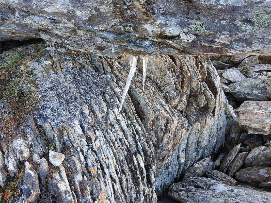
The icicle seen in the above photo hangs off the bottom of the north end of block 1 of IF-09. Block 1 rests on bedrock that has been eroded by ice extrusion and shows the characteristic grooved pattern. It was not determined whether or not the bedrock supporting the north end of block 1 has undergone frost heave.
The above photo shows a small rock outcrop with a deeply grooved erosion pattern similar to erosion patterns seen on the west-facing blocks of IF-09. The east side of the group of blocks comprising IF-09 is seen to the upper left of the frame.
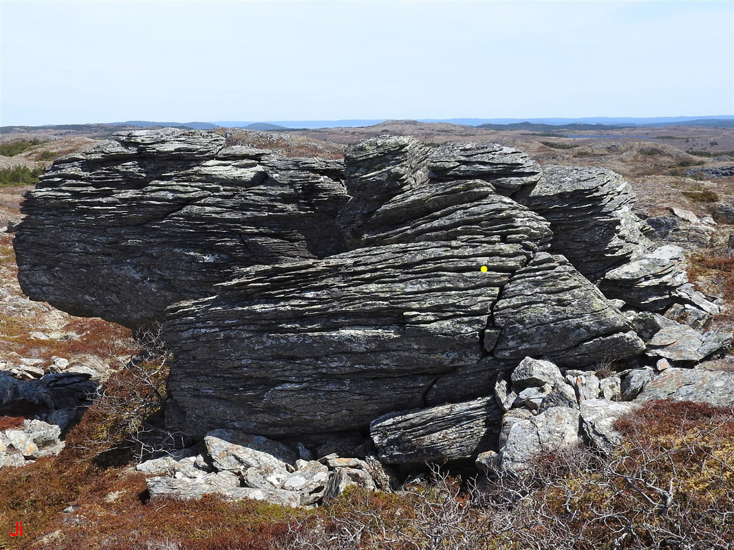
The block with the grooved surface seen near the center of the above frame lies 10 m southwest of IF-09 (IF-09 seen in left background). This block appears to be a fragment that originated alongside the blocks comprising IF-09, but the block was transported further upward into cold glacial ice that was deforming by creep. The block was subsequently carried down ice in a deformational (not a sliding) flow. For the purposes of the following discussion, this block will be designated as block F.
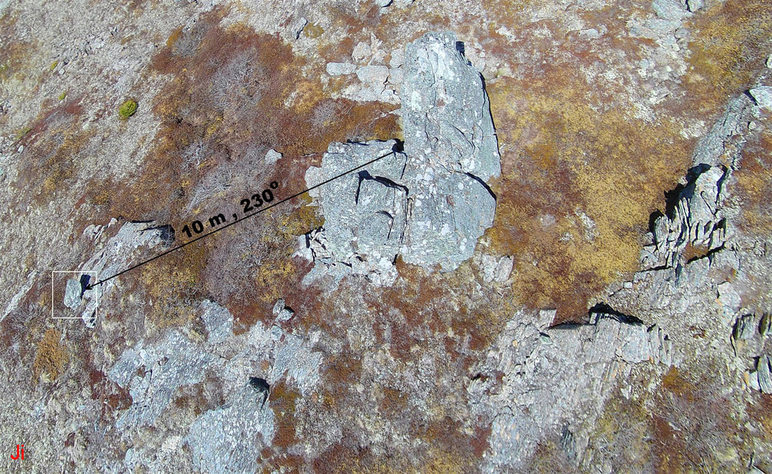
Block F is outlined with a white rectangle in the above overhead photo. The indicated direction of glacial transport of block F, 230 degrees true, was referenced from an arbitrarily designated point of origin near the center of IF-09. In reality, the block would have traveled from a point of origin in bedrock to the east of the location where IF-09 now sits. The direction of glacial transport of block F does not differ significantly from the direction of transport of the blocks comprising IF-09. Other indicators in the local area also point to an average velocity of glacial ice creep trending in a generally westerly to southwesterly direction.
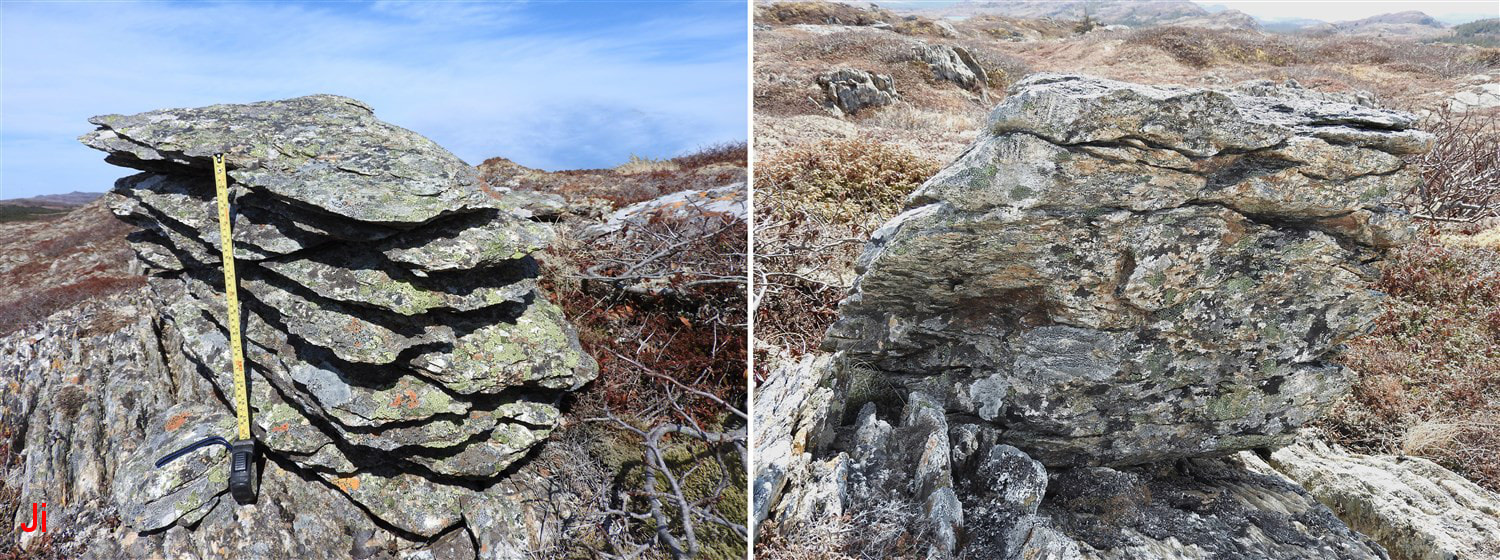
The photos above show two views of block F, taken from 180 degree opposing directions. Block F resembles blocks B, C, and E found at the IF-09 site, both in terms of its asymmetrically eroded surfaces and its present orientation. The block was tested for mechanical integrity and found to be intact, with no loose or detached layers. The depth and density of grooves on the west side of Block F resembles the pattern of grooves seen on block C. Block F can reasonably be assumed to have been part of the bedrock outcrop that was the precursor to IF-09. The grooves on block F were formed by subglacial ice extrusion, and the opposing side of block F, showing widened incomplete joints, was a surface where water/ice entered the block.
If it is accepted that block F originated in the same event that formed IF-09, then the displacement of block F becomes an indicator of the magnitude and direction of glacial ice deformational flow at a height that was probably just a few meters above ground. Assuming that block F was separated from bedrock during the Younger Dryas cold interval, then about 15 meters of lateral ice translation via deformation occurred over a time interval less than or equal to about 1000 years at a height of perhaps 2 to 5 meters above the ground.
If it is accepted that block F originated in the same event that formed IF-09, then the displacement of block F becomes an indicator of the magnitude and direction of glacial ice deformational flow at a height that was probably just a few meters above ground. Assuming that block F was separated from bedrock during the Younger Dryas cold interval, then about 15 meters of lateral ice translation via deformation occurred over a time interval less than or equal to about 1000 years at a height of perhaps 2 to 5 meters above the ground.
|
|
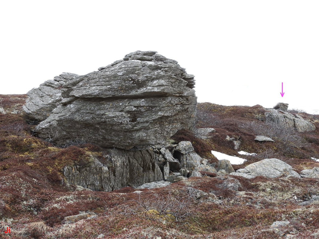
Both of the above photos show IF-09 and external feature, block F. Block F is indicated by the magenta arrow in the second (right) view above, taken from northeast of the IF-09 site. The trajectory of block F provides an opportunity to directly observe the qualitative effect of deformational ice motion in a cold-based glacier. The lack of rotation of block F about a vertical axis while it was being transported suggests that the ice velocity field just a few meters above the ground was homogeneous. Other indicators of ice creep very close to the ground (height less than 20 cm) at locations near to IF-09 imply a much less homogeneous pattern of glacial ice deformation.
|

|
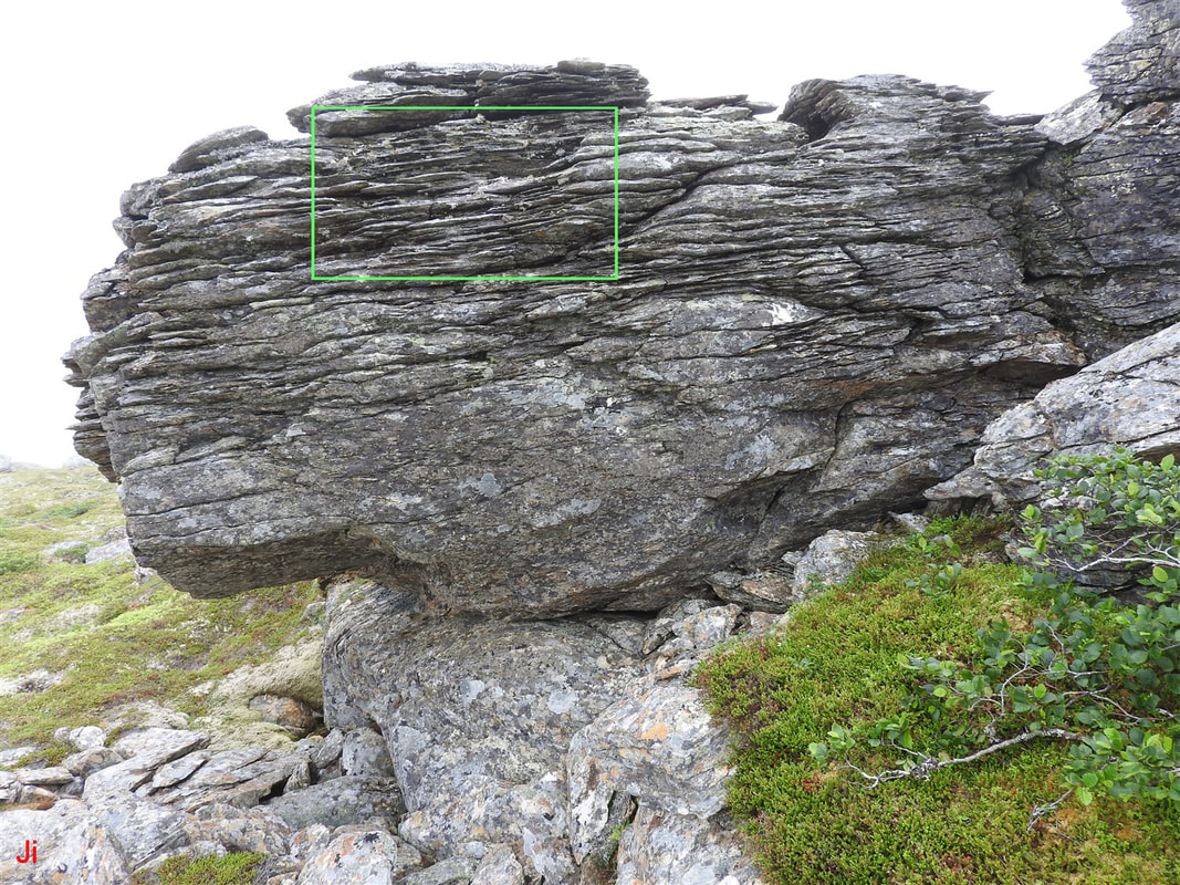
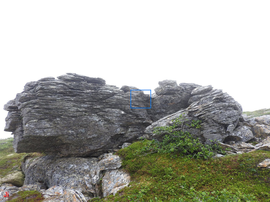
The first (left) photo above shows IF-09, viewed from the north, and an area of exposed bedrock to the east of IF-09. The bedrock east of IF-09, shown in more detail in the second (right) photo above, includes an area of flat, sloping bedrock surface that presumably mates with an equivalent area of flat surface on the east side of block 1. Just south of the area of flat, sloping bedrock seen in the second (right) photo above, is an area of frost-heaved bedrock. This frost-heaved bedrock is shown in the closeup below.
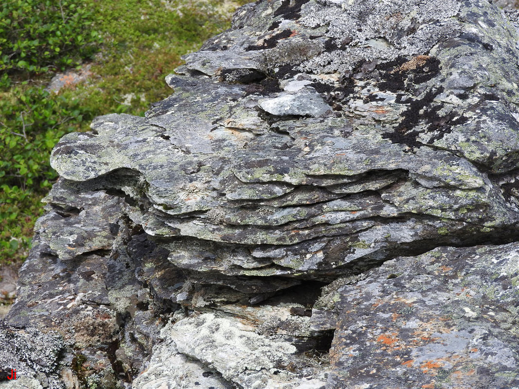
The frost-heaved monolith shown in the above photo has been delaminated by ice extrusion in a manner closely matching the erosion seen on the west-facing (former top) surfaces of blocks comprising IF-09. The monolith sits beside an area of sloping bedrock that shows no pronounced evidence of erosion by ice extrusion. The appearance of a frost-heaved monolith sitting adjacent to bedrock that has not been disrupted by ice is unsurprising. Bedrock frost heave is an unstable process and once ice begins to segregate in a cavity in bedrock, a resulting positive feedback loop concentrates ice segregation at the one site.
It is more puzzling that the rock adjacent to the delaminated monolith is not equally delaminated. Unless groundwater penetration showed an abrupt spatial boundary, erosion by ice extrusion would be expected to occur beside the monolith, as it occurred within the monolith. This is because delamination of the monolith would be expected to largely finish before the base of the monolith separated from bedrock. With the base of the monolith still attached, there would be no real boundary between the monolith and the adjacent bedrock. The delamination of the monolith by pore water intrusion and ice segregation is a process that would be expected to slow once a lens of segregated ice developed underneath the monolith, cutting off pore water feed.
The probable reason for the abrupt change in the pattern of bedrock erosion when moving from the monolith to the adjacent bedrock is that the adjacent bedrock surface was confined by overlying rock. This relatively flat bedrock surface follows a plane of rock failure and separation. Pore water moving across the failure plane before rock failure occurred would be moving in a confined environment that would inhibit ice segregation. When block 1 of IF-09 separated from bedrock along the failure plane, the rock at the newly-exposed surface would become less confined. However, by the time block 1 separated, the groundwater intrusion event that generated ice extrusion erosion patterns at the site might have been largely completed. A timeline for the ice-induced bedrock disruption would thus incorporate: 1) Groundwater intrusion, ice segregation, erosion by ice extrusion in lesser confined rock; 2) Bedrock frost heave, detachment of the blocks comprising IF-09 from bedrock, cessation of groundwater intrusion; 3) Glacial transport of the blocks comprising IF-09. All of the events just listed would have occurred beneath a thick, downwasting cold-based glacier.
|
|
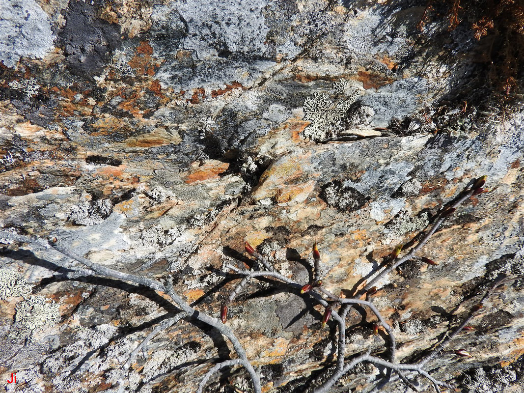
The second (right) photo above is a closeup of the area outlined with the small blue rectangle seen in the first (left) photo above. Examination of the closeup photo shows coarsely-spaced narrow grooves in the surface, presumably indicating water/ice channels penetrating the rock. As suggested above, a possible explanation for why these grooves were not appreciably widened was that groundwater migration tapered off not long after blocks 1 and 2 of IF-09 separated from bedrock.
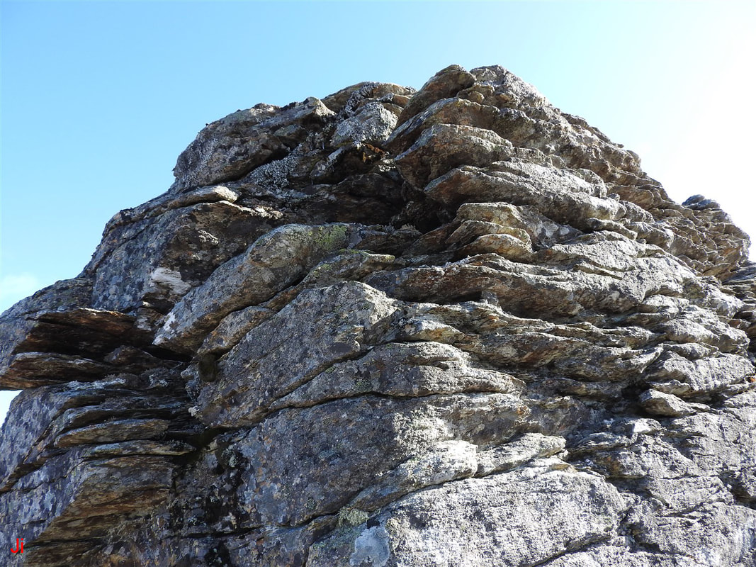
The above photo shows a south-looking view of the previously described areas of frost-heaved bedrock abutting flat, sloping bedrock lying east of IF-09. A rock sample was obtained from the frost-heaved area (location just right of the field of view shown above) by pulling out a delaminated block that had detached at the base and was left suspended between two adjacent delaminated frost-heaved monoliths. This sample was examined and photographed and is described below.
Rock specimen showing bedrock erosion by subglacial ice extrusion
A thin block of delaminated frost-heaved bedrock was extracted at the location shown above beneath the arrow. The location is about 6 m east of IF-09 in a section of ice-disrupted bedrock that abutted the site of origin of IF-09 and was presumably affected by the same groundwater intrusion as affected IF-09. The extracted block is pictured below.
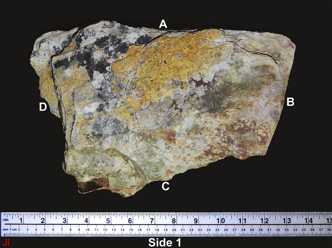
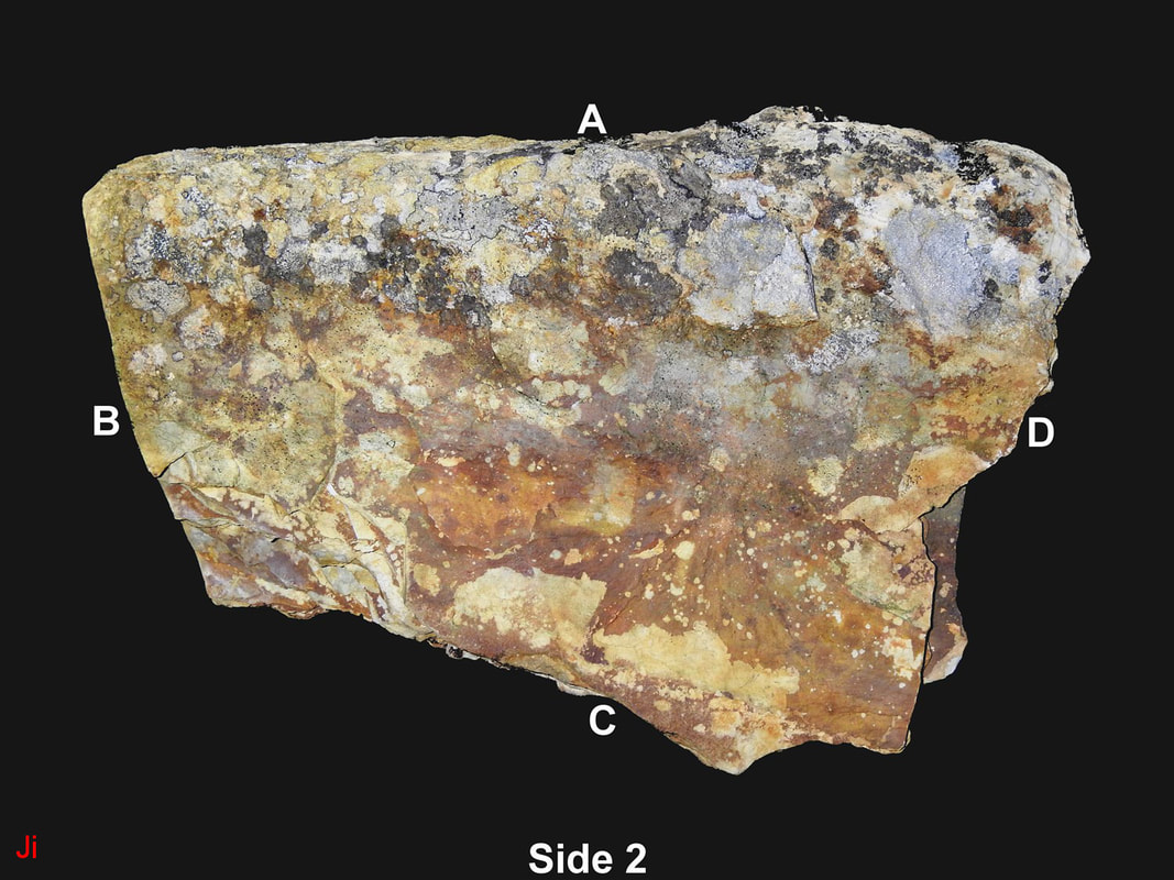
The edges of the frost-heaved specimen are labelled in the above two photos. Edge A is the top of the specimen.
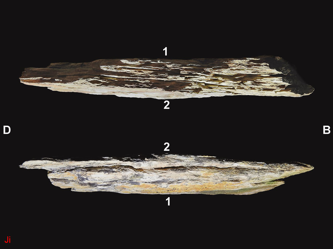
The above photo shows edge C (bottom) in the first image, and then edge A (top) below. The numbers and letters indicate the other sides and edges. The top edge of the block demonstrates a single groove presumably formed by subglacial ice extrusion. The groove appears to have been rounded by the action of rainfall or lichen or both, during the Holocene.
The bottom edge demonstrates the fine-scaled delamination of the specimen. This delamination is better revealed in the oblique-angled photo shown below.
The bottom edge demonstrates the fine-scaled delamination of the specimen. This delamination is better revealed in the oblique-angled photo shown below.
The clear delineation of the layers visible on the bottom edge is a consequence of the tearing of the block away from underlying rock. It was not clear how the block came to be torn from the rock beneath, but one likely possibility is that the frost-heaved block was side-loaded by glacial ice and broke off flush with the ground.
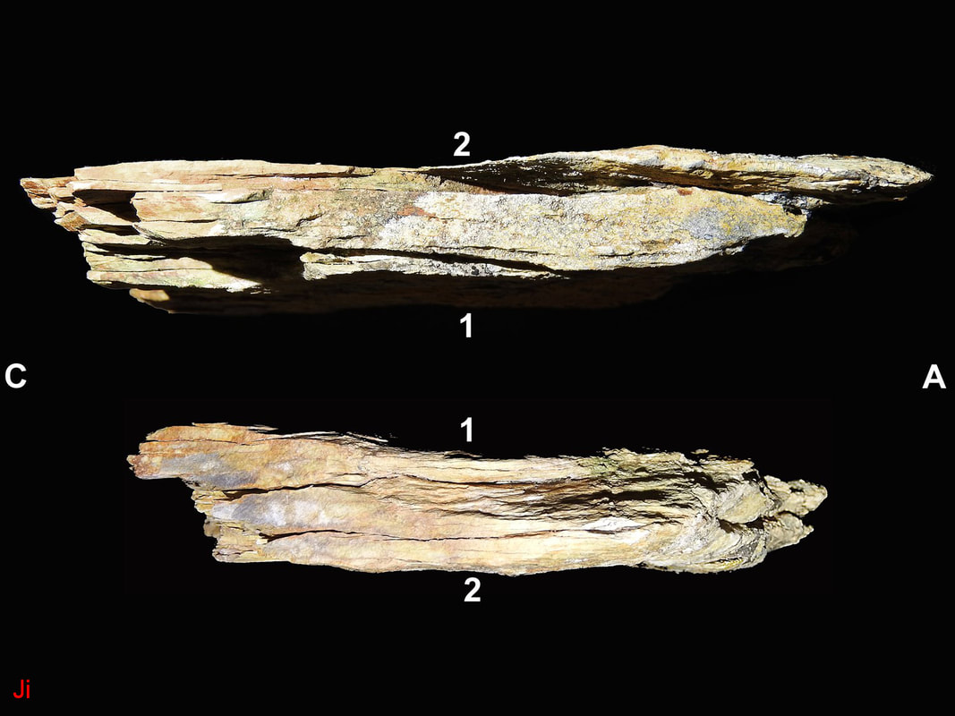
The two side edges shown above reveal channels (widened joints) that carried water/ice toward the top of the block. One prominent channel connects with the top groove. Although the visibly widened joints appear to traverse the full breadth of the specimen, they do not allow the specimen to readily break apart along the apparent planes of weakness. This incomplete delamination is a potentially useful indicator of widened joints that have been formed by subglacial ice segregation rather than by other stresses (for example, subaerial frost wedging) that might have affected the rock.
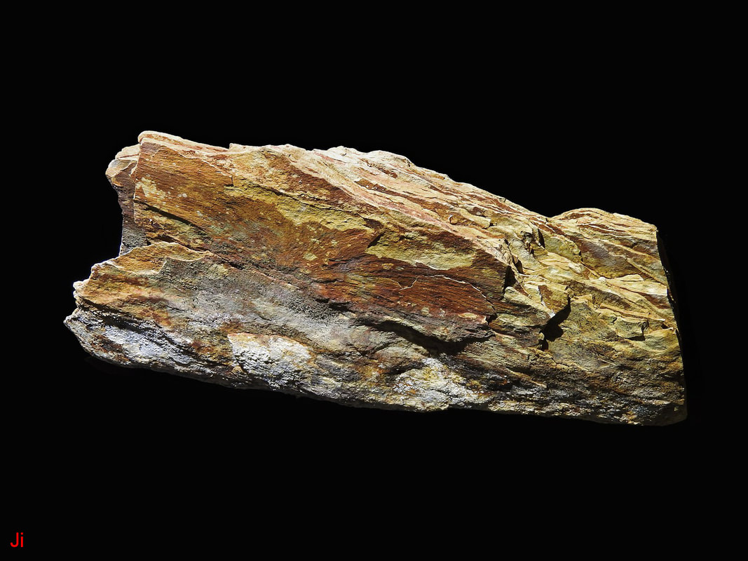
In cursory examination, the rock specimen seen above might be construed to resemble slate in its texture. In slate, regional metamorphism acting alone is sufficient to align microcrystals of phyllosilicate minerals in a manner that allows the rock to be delaminated readily with externally applied stress. The rock comprising the specimen shown above does not possess the texture of slate. In areas where obvious ice-induced disruption of similar rock has not occurred, the rock is highly resistant to mechanical delamination and the rock will not fracture like slate. In areas where the rock has been disrupted by ice, the rock can be mechanically delaminated with some difficulty, often cleaving along irregular surfaces or fracturing along surfaces that cross the planes of foliation. It appears as though micro-scale frost wedging processes can efficiently partially delaminate the rock, in general trending with the foliation, but acting only along irregular and incomplete pathways.
In cursory examination, the rock specimen seen above might be construed to resemble slate in its texture. In slate, regional metamorphism acting alone is sufficient to align microcrystals of phyllosilicate minerals in a manner that allows the rock to be delaminated readily with externally applied stress. The rock comprising the specimen shown above does not possess the texture of slate. In areas where obvious ice-induced disruption of similar rock has not occurred, the rock is highly resistant to mechanical delamination and the rock will not fracture like slate. In areas where the rock has been disrupted by ice, the rock can be mechanically delaminated with some difficulty, often cleaving along irregular surfaces or fracturing along surfaces that cross the planes of foliation. It appears as though micro-scale frost wedging processes can efficiently partially delaminate the rock, in general trending with the foliation, but acting only along irregular and incomplete pathways.
Summary
Illustrative Feature 09 shows erosion artifacts that can be interpreted with a reasonably high degree of confidence as having resulted from subglacial erosion processes rather than Holocene erosion processes. The confidence stems from the size of the blocks comprising the feature and their proximity to a recognizable indentation in bedrock that reliably indicates their point of origin. The blocks comprising IF-09 were rotated by 90 degrees about a horizontal axis, thereby realigning their prominent foliation at right angles to foliation in the local bedrock. IF-09 is composed of a fine-grained sedimentary rock lacking discernible bedding and appearing homogeneous throughout.
The blocks comprising IF-09 show distinctive grooved erosion patterns that vary strongly depending on compass direction and position on the blocks. The variations show a consistent pattern, with surfaces identified with the original tops of the blocks showing the deepest, widest and most numerous grooves. The eroded grooves seen on IF-09 closely resemble grooves seen on nearby ice-disrupted bedrock, differing only in orientation, with grooves following vertical planes in the bedrock and horizontal planes in the blocks comprising IF-09.
The asymmetry seen in the eroded grooves on IF-09 can best be explained by interpreting the erosion patterns as having originated before the blocks comprising IF-09 were rotated by glacial action. Given that the grooves were formed beneath glacial ice, they imply ice movement in a direction normal to the surface of the rock, hence they imply subglacial ice extrusion. Grooved erosion patterns showing characteristics similar to those seen on IF-09 can be found over wide areas, usually in conjunction with other distinctive artifacts of subglacial bedrock disruption by extruded ice, most notably, frost-heaved monoliths. Bedrock erosion by ice extrusion, exemplified by the erosion patterns seen on the blocks comprising IF-09, appears to be the most widespread readily observable indicator of the past interaction of artesian groundwater and cold-based glacial ice on the Avalon Peninsula.