| Heart of Avalonia |
Frost-heaved Bedrock: Illustrative Feature 02
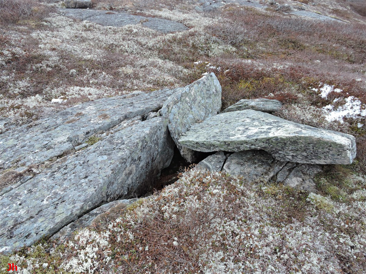
Joint block dislodged from bedrock by frost heave,
shifted by glacial ice.
This feature provides an example of where hydraulic bedrock frost heave appears to have taken place beneath a cold-based glacier.
Isthmus of Avalon
Joint block dislodged from bedrock by frost heave,
shifted by glacial ice.
This feature provides an example of where hydraulic bedrock frost heave appears to have taken place beneath a cold-based glacier.
Isthmus of Avalon
The purpose of this Illustrative Feature 2 (IF-02) is to demonstrate that large-scale bedrock frost heave has taken place under cold-based glacial ice at a specific location on the Isthmus of Avalon, Newfoundland. This feature, along with IF-01 and others to follow in the Illustrative Features series, will help build the case that a local area exceeding 1 sq. km was affected by abundant and widespread hydraulic frost heave occurring under thick cold-based ice cover. The overriding theory is that the affected area was located near the edge of a steep polythermal glacier that developed along the spine of the Isthmus of Avalon as rapid deglaciation gave way to an abrupt onset of cold-climate conditions.
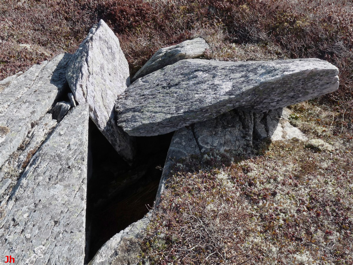
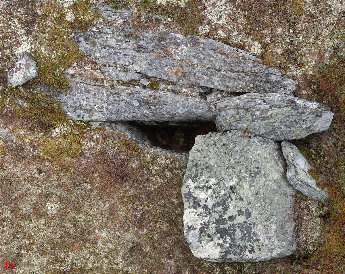
IF-02 consists of a large joint block, fully dislodged from an underlying cavity in bedrock, as well as the cavity itself and the geometry of the overall layout.
IF-02 consists of a large joint block, fully dislodged from an underlying cavity in bedrock, as well as the cavity itself and the geometry of the overall layout.
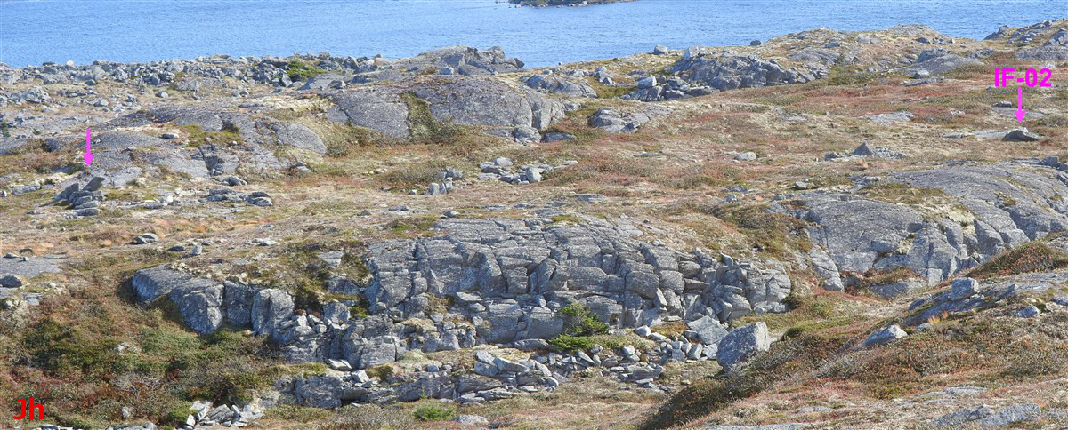
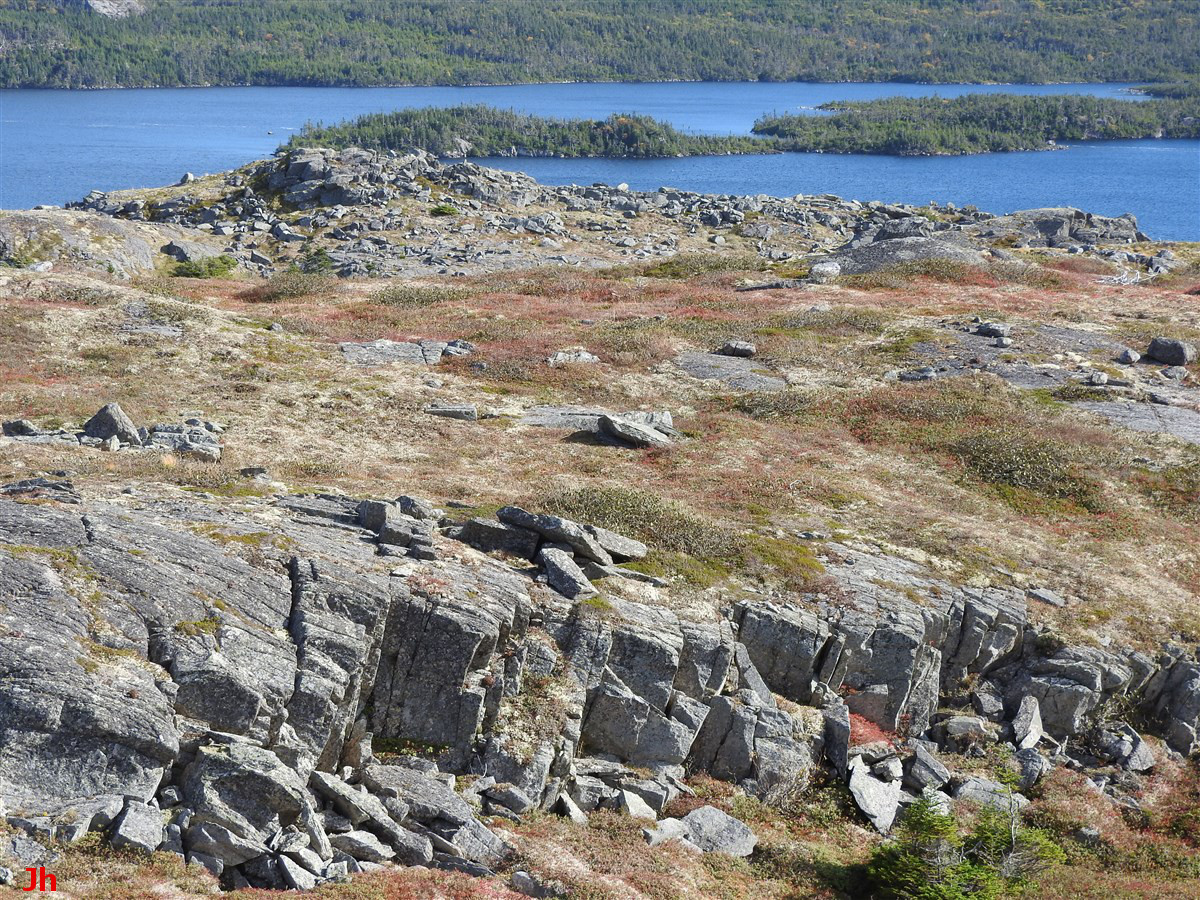
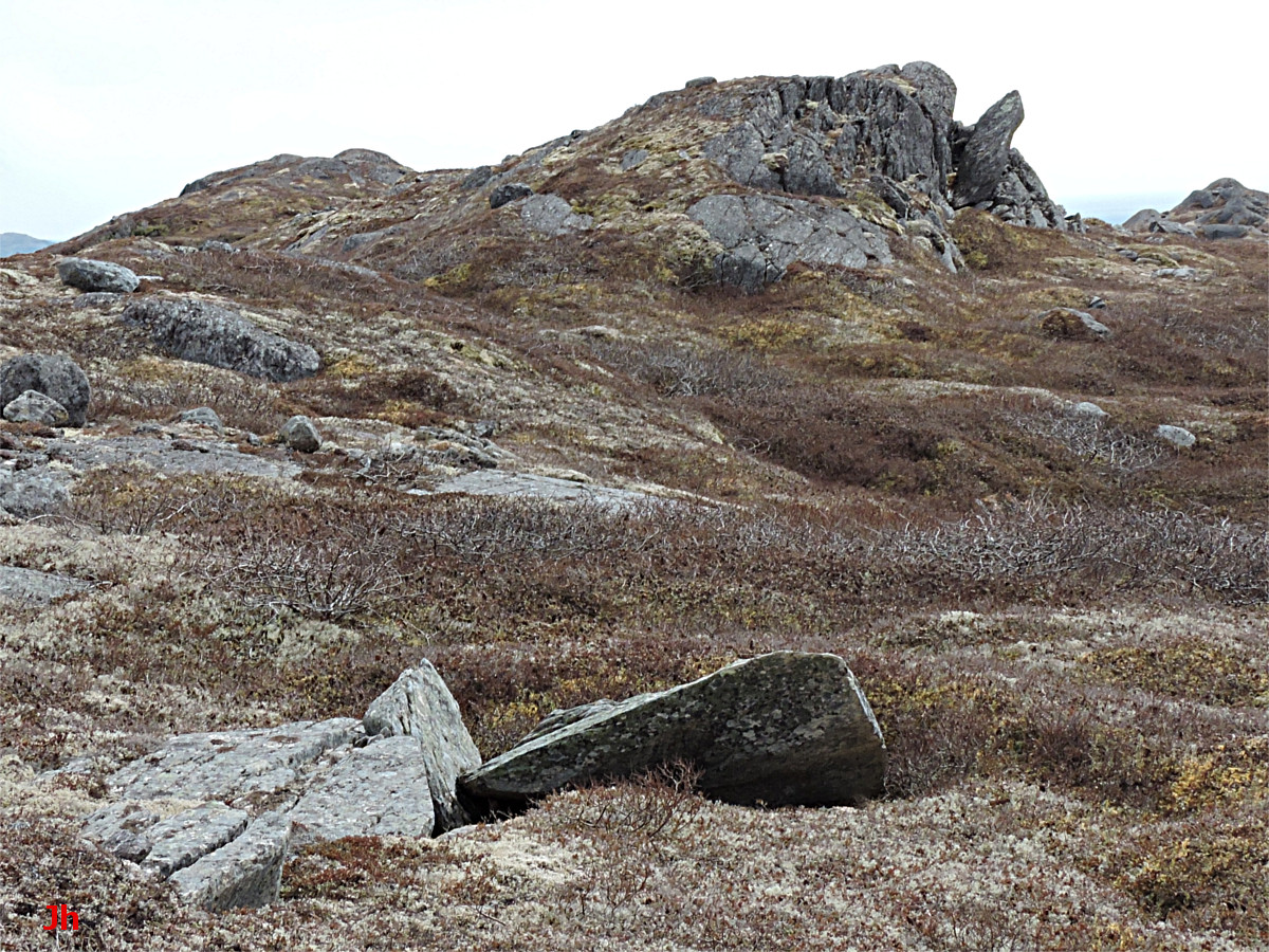
The two photos above show the surroundings of the frost-heaved joint block IF-02. The feature of interest (IF-02) is located at the exact center of the frame in the second photo. The first photo shows IF-02, along with another frost-heaved bedrock formation located below the arrow at the left of the field of view. The distance between the two arrows is 40 m. The lake in the background is 500 m east of IF-02 and at an elevation 70 m lower. IF-02 lies 310 m SSW of Illustrative Feature IF-01 presented previously.
The foregrounds of both photos above show bedrock smoothed by basal-slip glacial erosion giving way to plucked bedrock. The plucking reveals failure planes following both longitudinal cleavage (facing the camera) and cross jointing (at right angles to the cleavage). The rock fragments dislodged by plucking have remained close to their original source. The bedrock is schistose volcanic rock (metasomatized tuff and ignimbrite).
The foregrounds of both photos above show bedrock smoothed by basal-slip glacial erosion giving way to plucked bedrock. The plucking reveals failure planes following both longitudinal cleavage (facing the camera) and cross jointing (at right angles to the cleavage). The rock fragments dislodged by plucking have remained close to their original source. The bedrock is schistose volcanic rock (metasomatized tuff and ignimbrite).
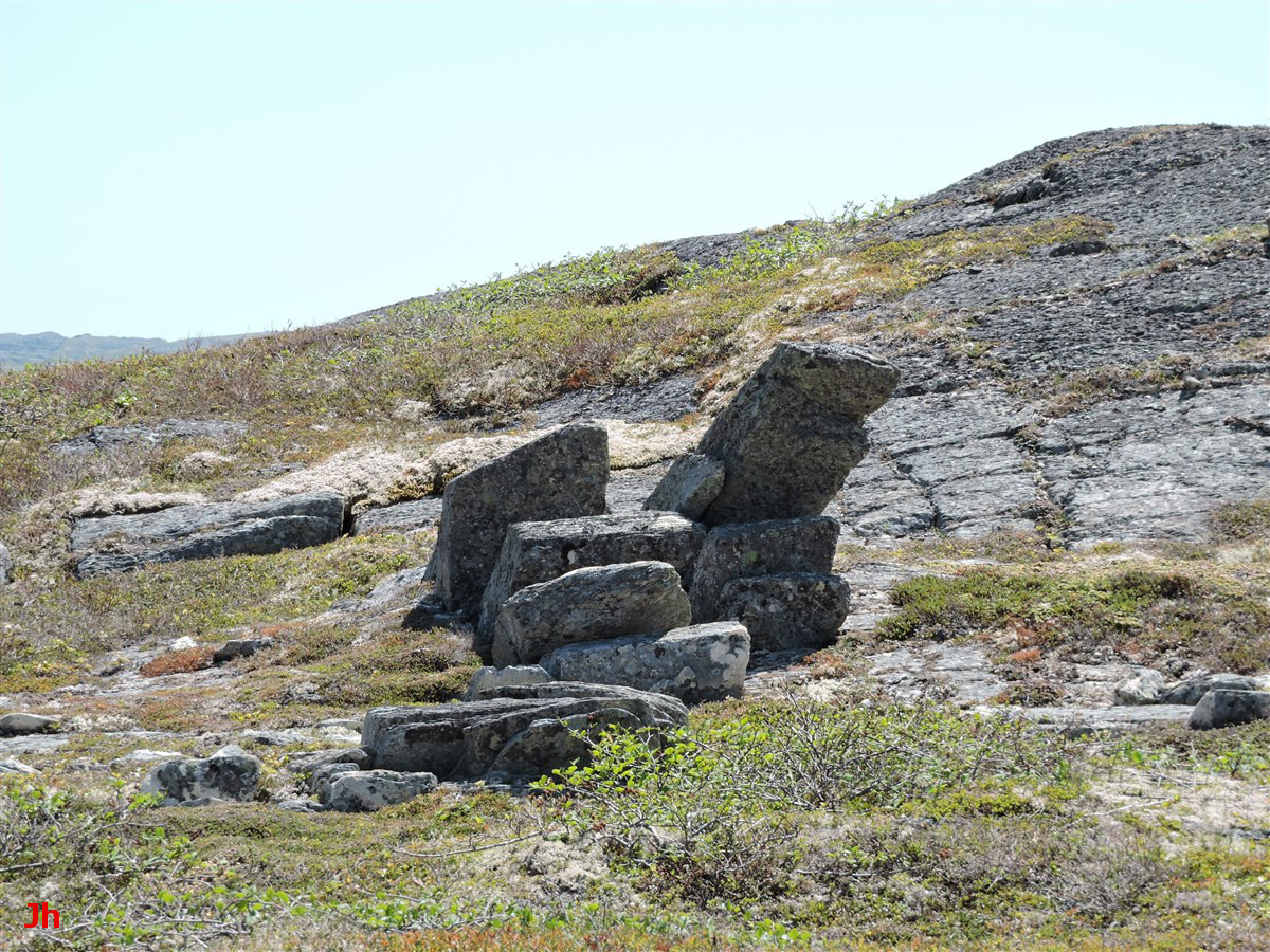
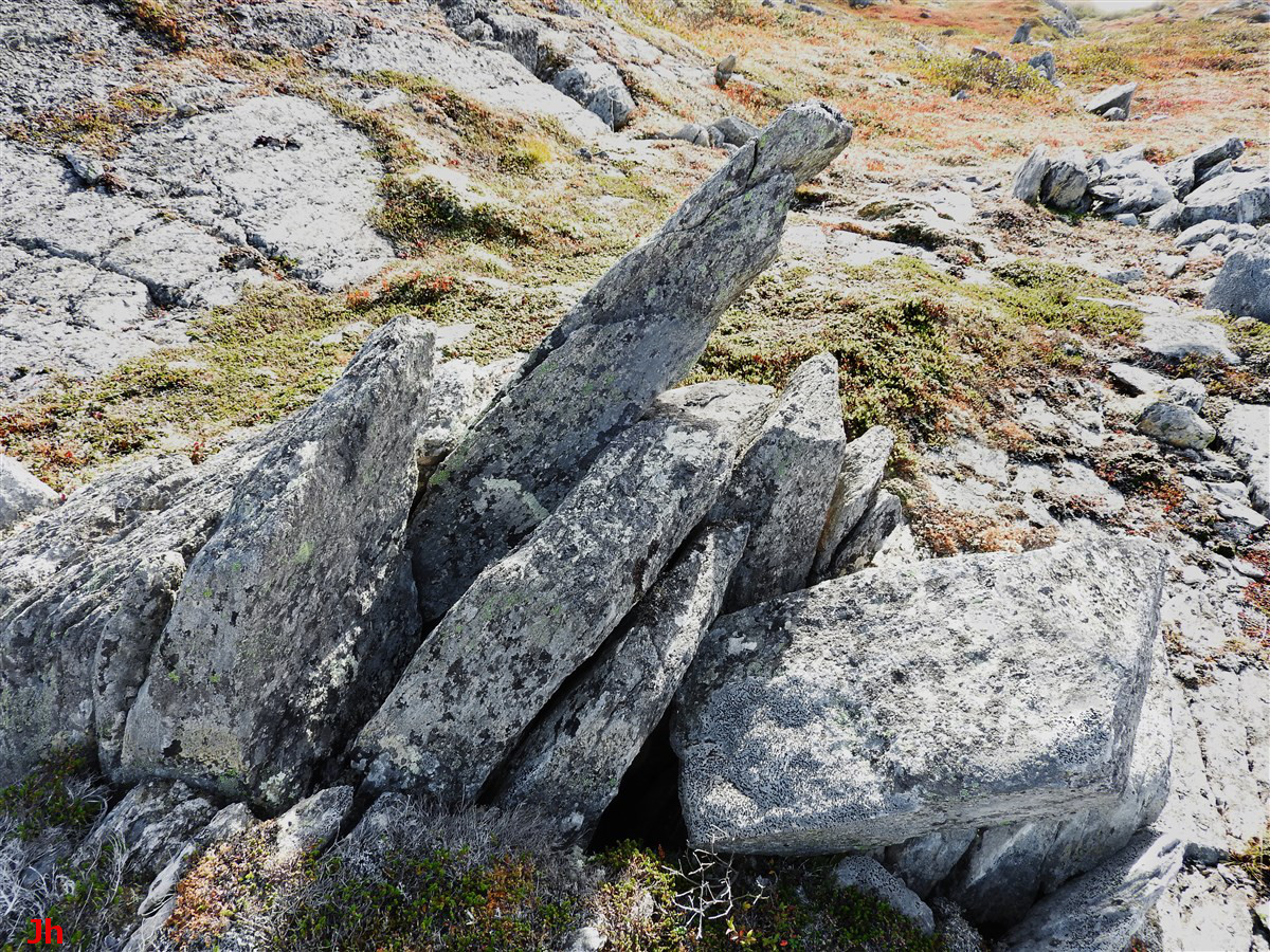
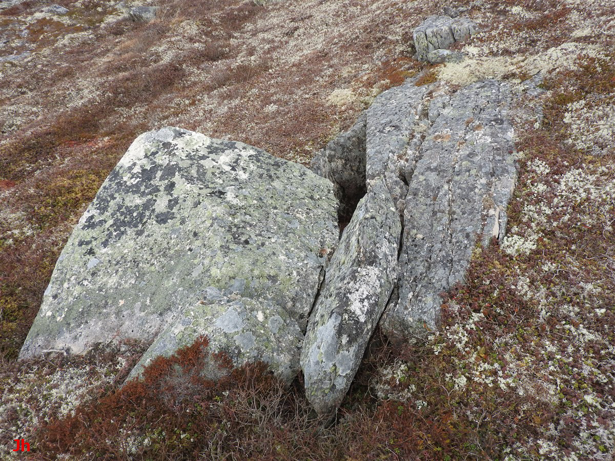
The above photos show two views of the frost-heaved bedrock formation lying 40 m north of IF-02 (under left arrow in picture appearing previously). The tallest joint block reaches 1.1 m above ground level. One of the joint blocks in the cluster (rightmost block, second photo) has been completely dislodged from the underlying bedrock and is aligned toward the direction of ice flow in this area.
The above picture looks south, with the dislodged frost-heaved joint block IF-02 in the foreground. Note the large (more than 3 m high) slab of rock that has been levered outward from the small hill in the background. This type of feature is common in the immediate area and demonstrates glacial plucking where the plucked rock is shifted only a very short distance from point of origin (see also IF-03).
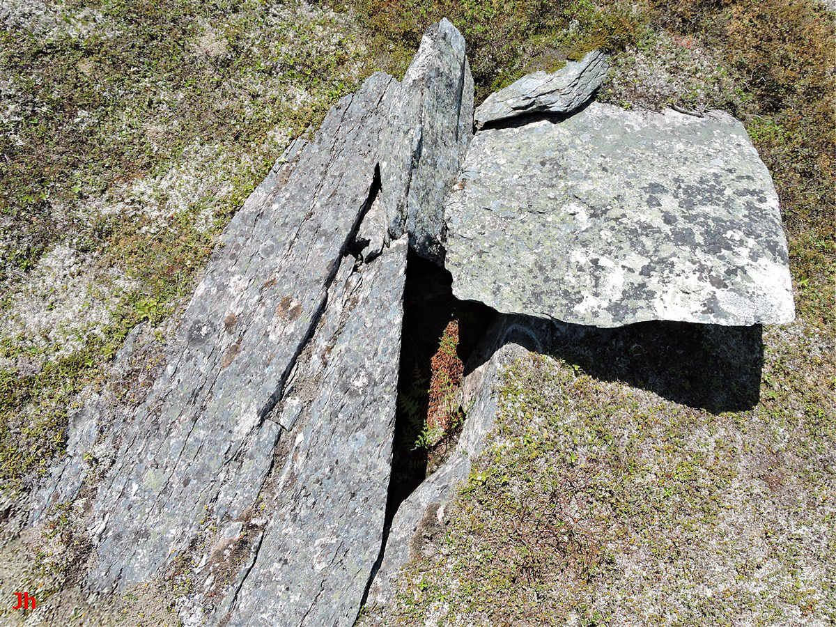
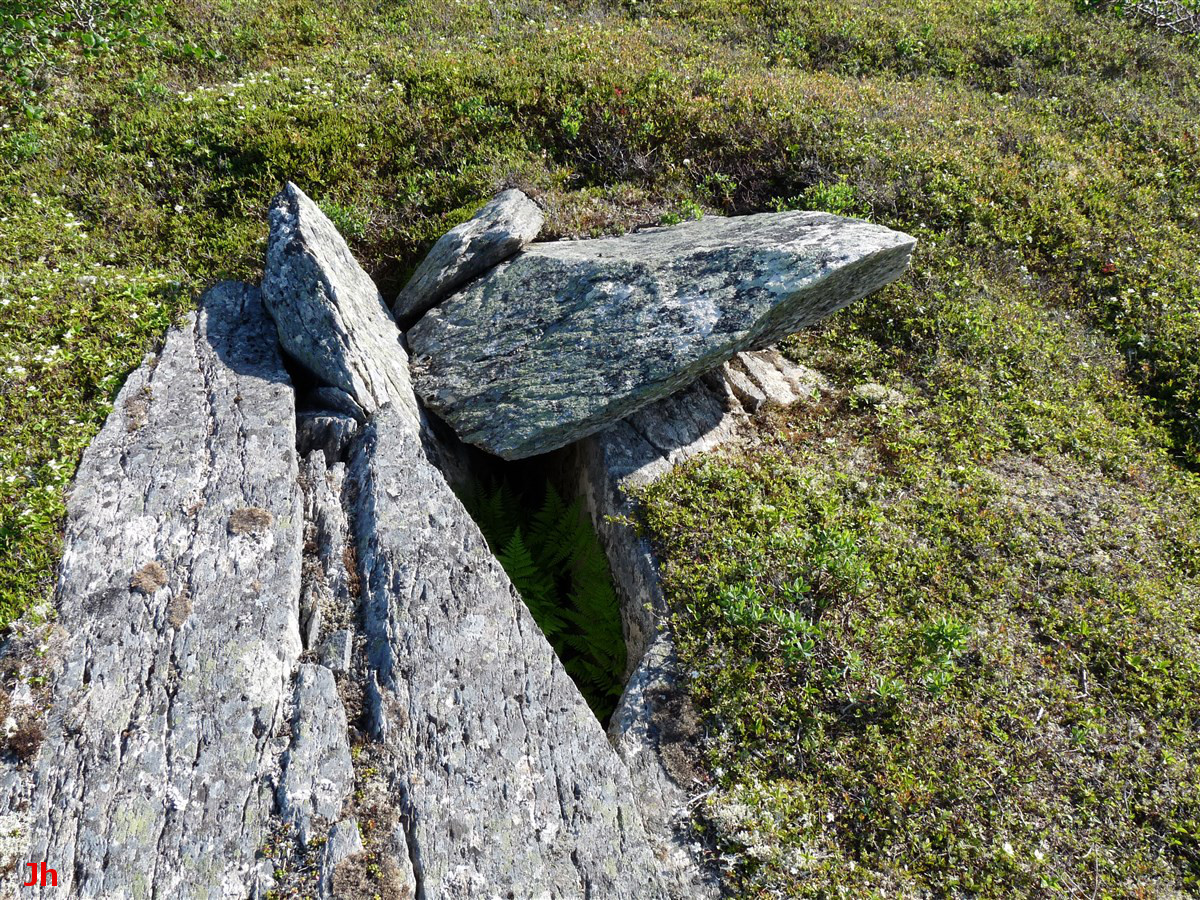
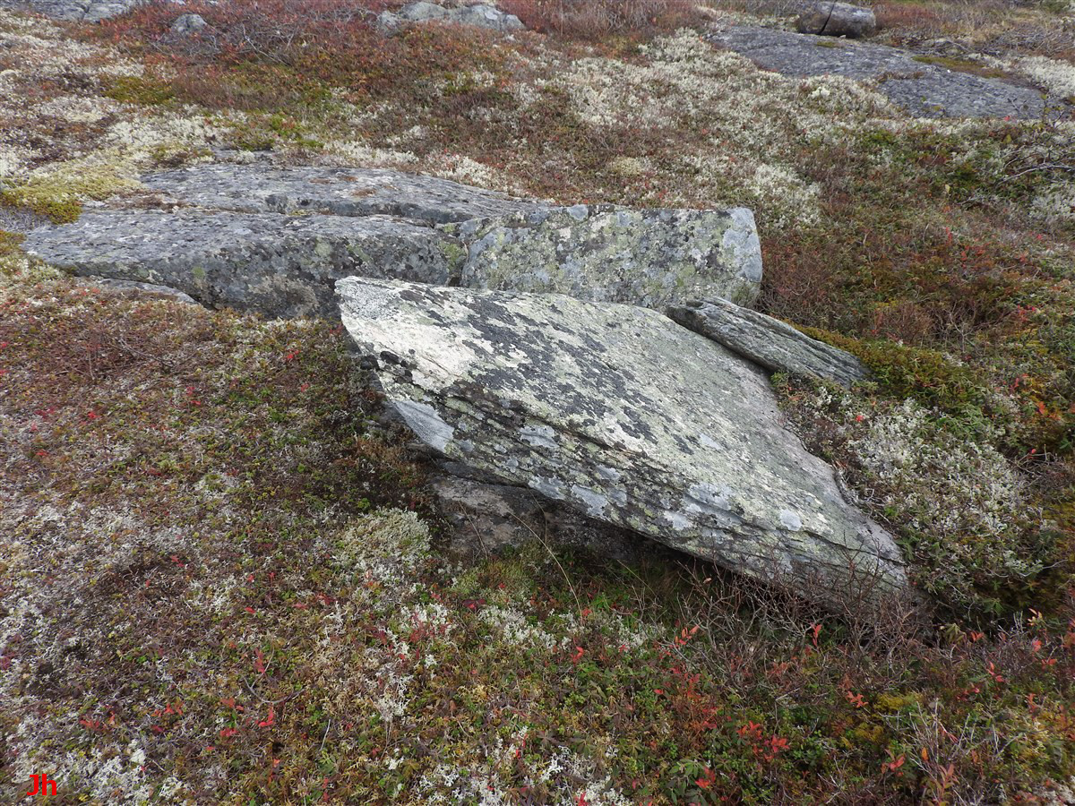
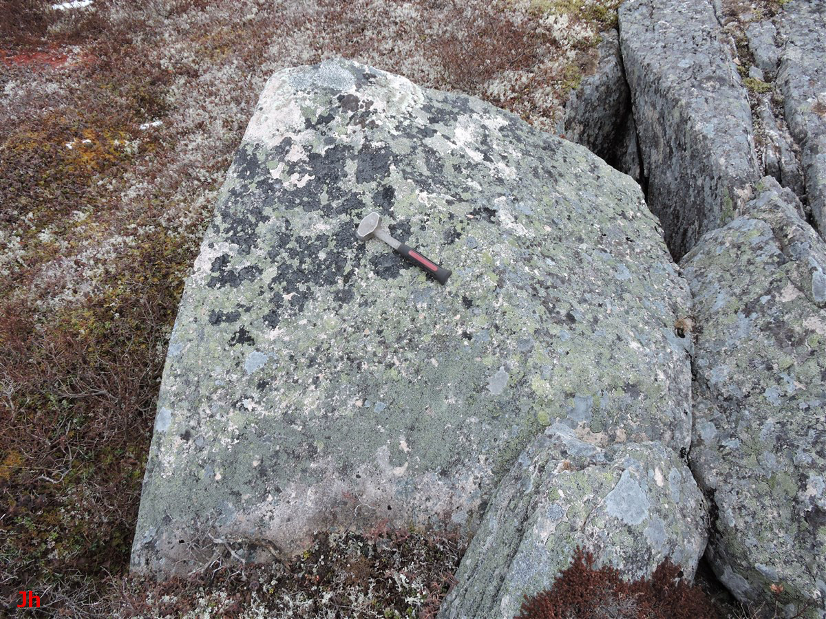
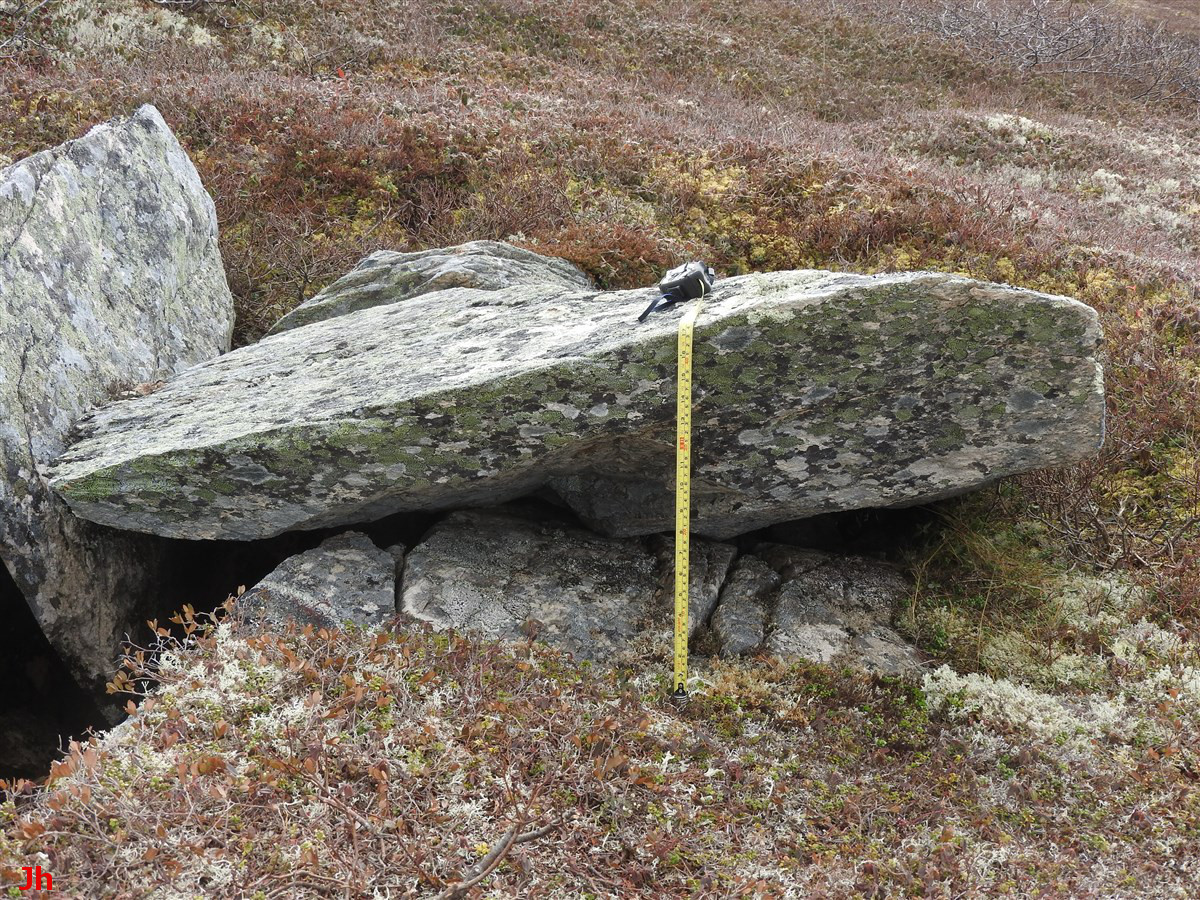
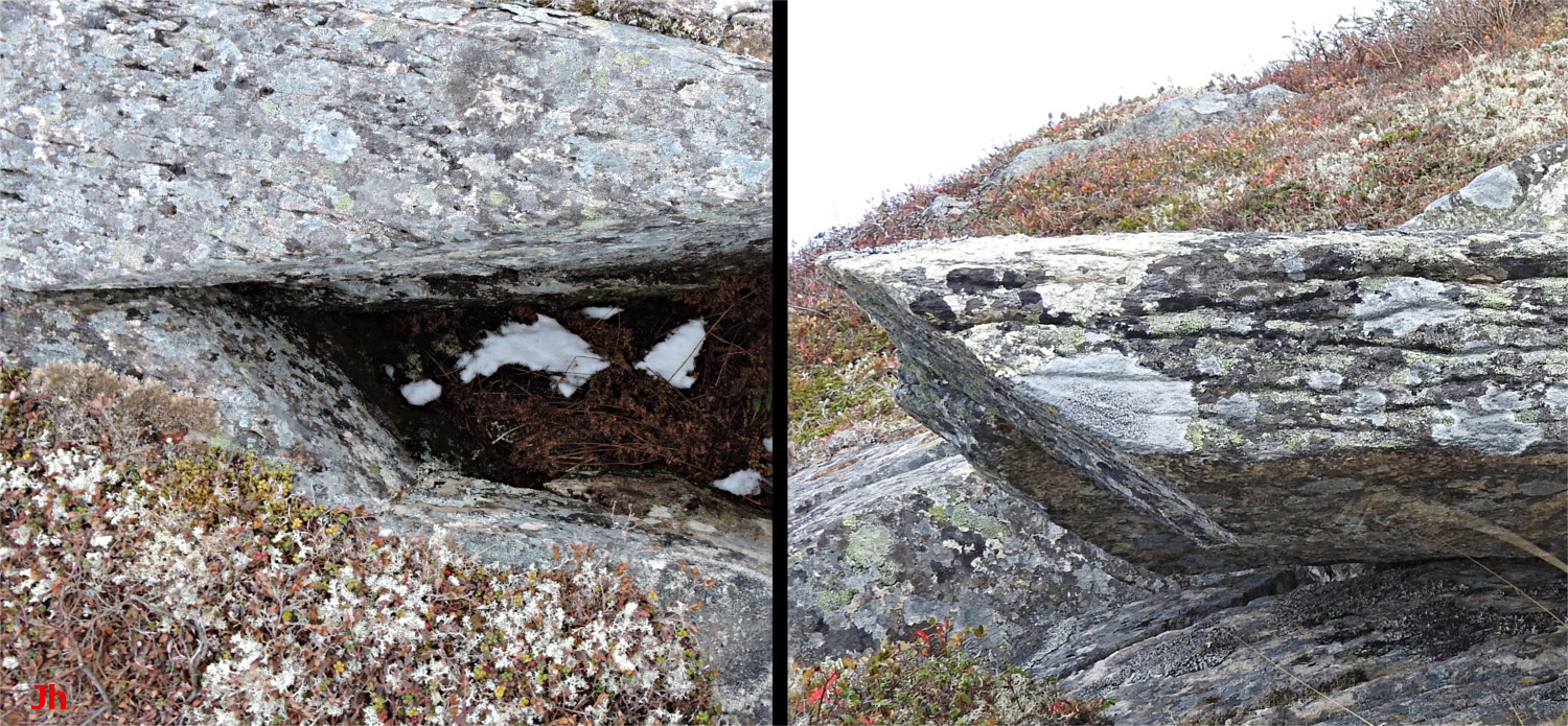
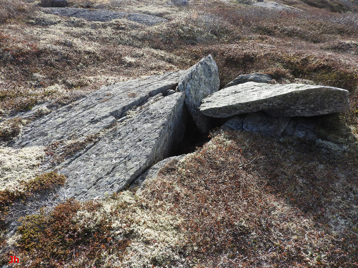
Four views of the dislodged joint block from different directions are shown above. The third (bottom, left) photo shows the former top surface of the joint block (recognized by the etched longitudinal cleavage) facing the camera.
The two photos above show scale. The hammer is 27 cm long. The measuring tape reads 44 cm at the point where it bends over the rock.
The distinctive shape of the north (bottom in above photo) end of the cavity from which the block was dislodged makes it straightforward to determine the original fit of the block into the cavity and hence to see how the block was shifted. The photo below compares a side view of the block with a top view of the cavity.
The photos and video below show the shift in the position of the joint block following initial frost heave and leading to the block's final toppled and displaced position.
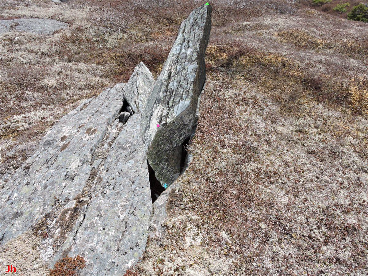
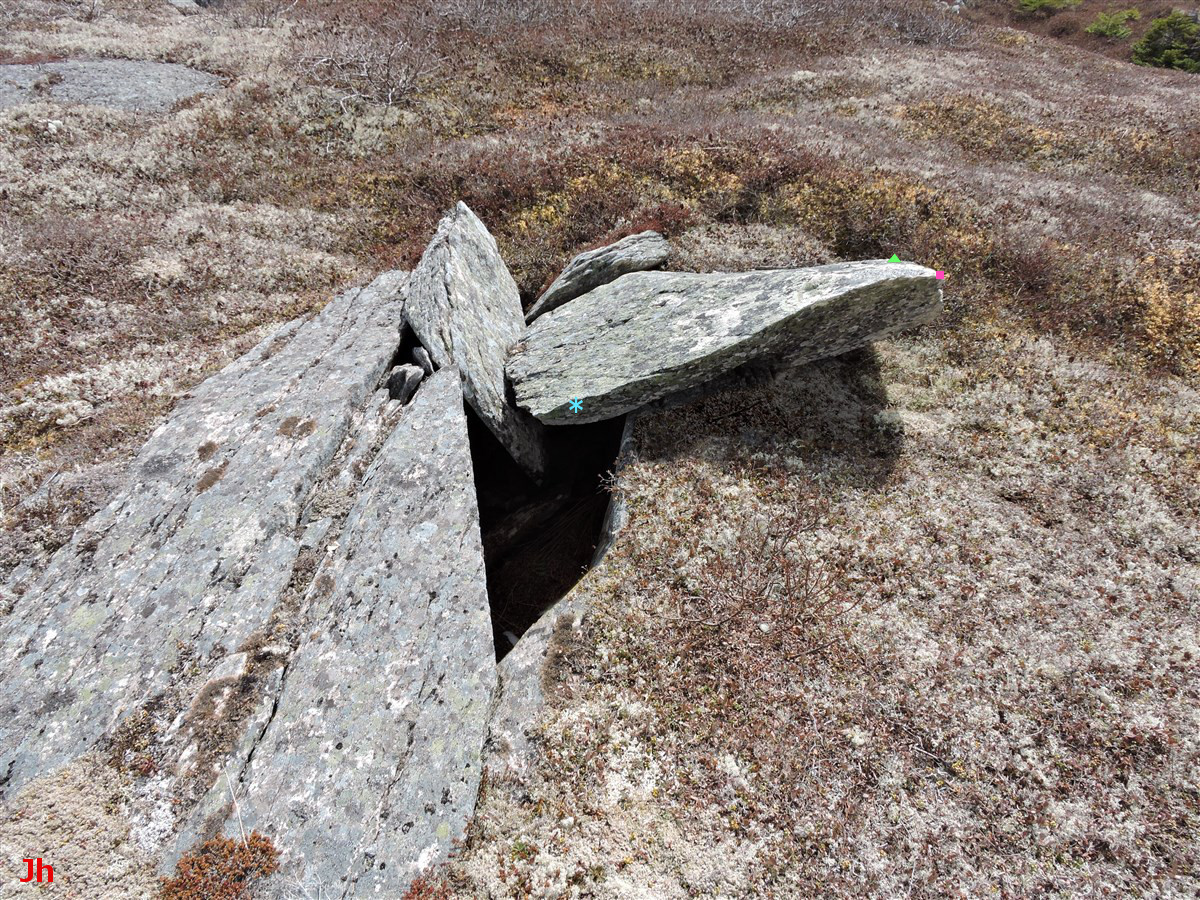
The digitally reconstructed image on the left was made by copying and rotating a side view of the dislodged joint block and then pasting the rotated section onto the view shown on the right. The three small colored symbols, green triangle, magenta rectangle, cyan asterisk, show the changes in positions of the corners of the block. Note that the block retreats from the camera as it tilts. The video below shows a two-frame animation of the positional shift depicted in the still photos above.
As illustrated above, the frost-heave/glacial process that displaced the joint block moved it first upward out of the surrounding bedrock and then moved it southward. A significant part of the block's total motion can be attributed to the sole action of gravity as the block tilted over to lie flat on the ground. The upward motion of the block can be attributed to conventional frost heave. It is the southward motion that requires the presence of moving glacial ice to combine with frost heave and gravity to yield the block's final position. An overhead view of the arrangement is shown below.
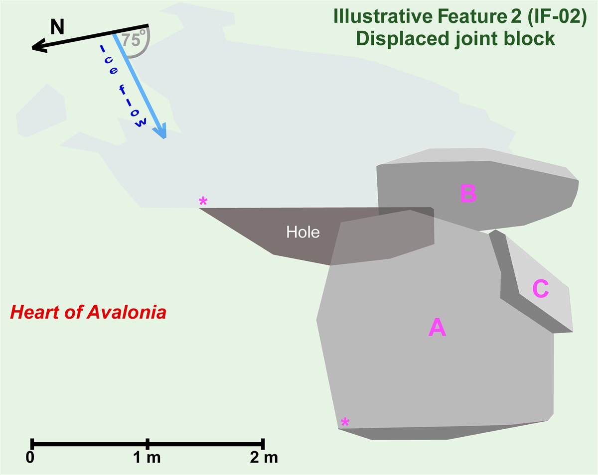
The diagram above provides an overhead view of the layout of the frost-heaved bedrock feature. The diagram was drawn in correspondence with the preceding overhead photo. The dimensions shown on the diagram are approximate and are distorted by perspective because of the relatively low altitude from which the overhead photo was taken. Block-A measured 2.0 m (left to right on diagram) by 1.45 m (top to bottom on diagram). The estimated weight of Block-A was 2500 kg. Block-B is a frost-heaved joint block that was not fully dislodged from bedrock. Block-C appears to be a piece that detached from the up-facing surface of Block-A and was then shifted by the action of ice or gravity.
The two asterisks both mark the position of the upper north-east corner of block-A. The top asterisk on the diagram shows initial position prior to frost heave while the bottom asterisk shows final position. The measured depth of the hole was 102 cm, but peat, vegetation and broken rock interfered with the measurement. The measured length of the hole was 2.0 m. The indicated direction of ice flow (255 deg. true) matches the direction measured in the local neighborhood (see IF-01) and also matches the direction measured from striations at this (IF-02) site. A photo showing the striations appears below.
The two asterisks both mark the position of the upper north-east corner of block-A. The top asterisk on the diagram shows initial position prior to frost heave while the bottom asterisk shows final position. The measured depth of the hole was 102 cm, but peat, vegetation and broken rock interfered with the measurement. The measured length of the hole was 2.0 m. The indicated direction of ice flow (255 deg. true) matches the direction measured in the local neighborhood (see IF-01) and also matches the direction measured from striations at this (IF-02) site. A photo showing the striations appears below.
In the above photo, striations made by basal-slip glacial erosion can be seen in the bedrock just left of the end of the gap nearest the camera and terminating at the gap. If the frost-heave and subsequent shifting of the dislodged block by ice motion occurred under cold-based glacial conditions, the striations suggest that the transition from basal-slip ice motion to creep-only ice motion did not involve a significant change in glacier flow direction at this location. Similar observations nearby support this theory (see IF-01).
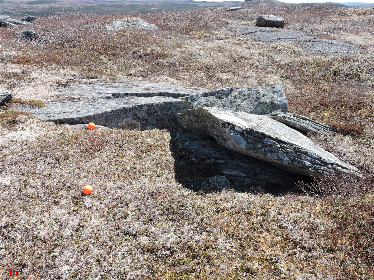
The orange balls seen in the above photo mark the expected position of the north edge of the large displaced joint block, had it simply toppled over. The distance from the expected position of this edge to the actual position is about 1 m. It is difficult to explain this horizontal motion without assuming the presence of moving glacial ice. The ground at the IF-02 site is level and ice flowing across this location would encounter a nearby downslope of just a few metres, before moving upward 30 m to crest a ridge. Because of the rugged, steeply sloping and variable topography of the immediate area, any ice sheet crossing IF-02 in the direction indicated would necessarily be at least several 10's of metres thick. Ice thickness in excess of 10 metres precludes any thermally-driven frost heave process (for example, ice segregation) that would exploit seasonal temperature gradients. This leaves hydraulic frost heave as the preferred explanation for the displacement of the joint block seen in IF-02.
heartofavalonia.org Exploring Geologic History
