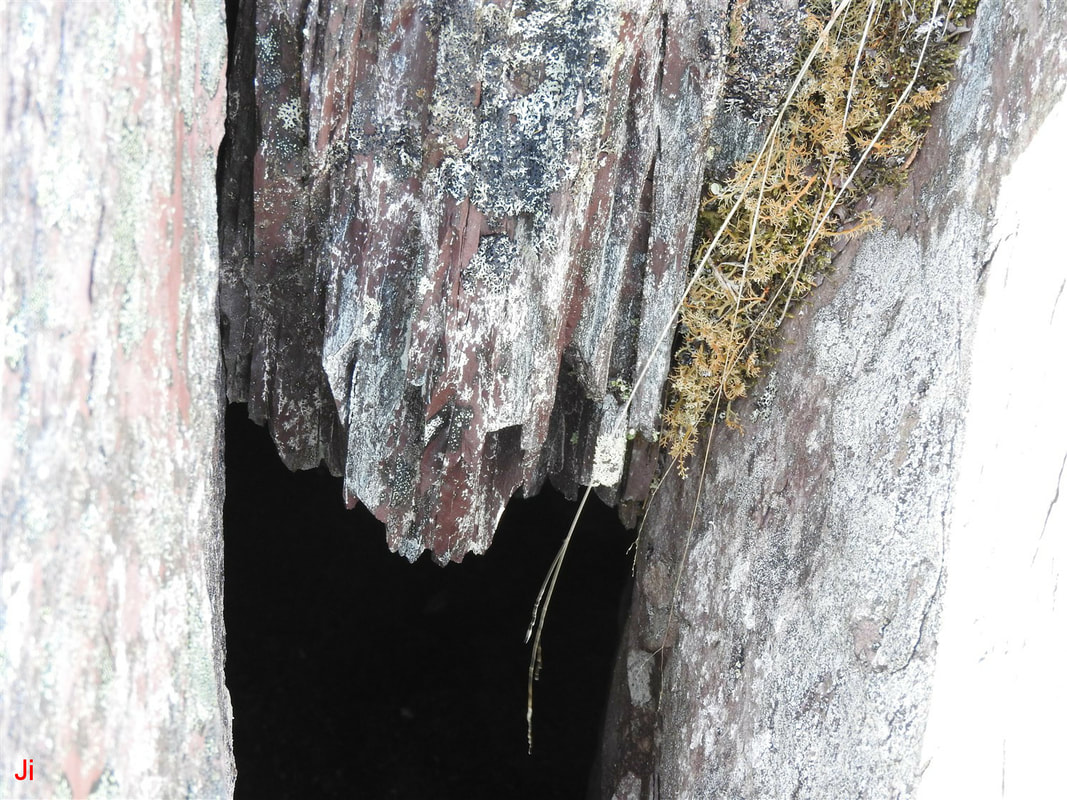
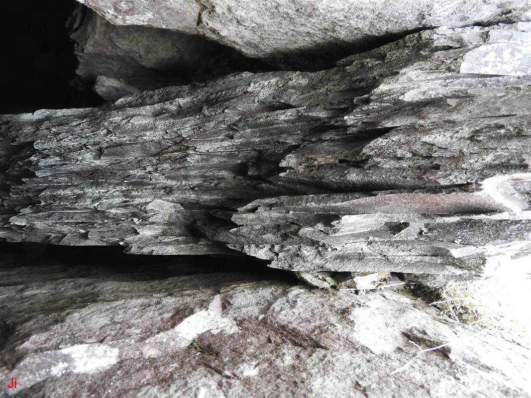
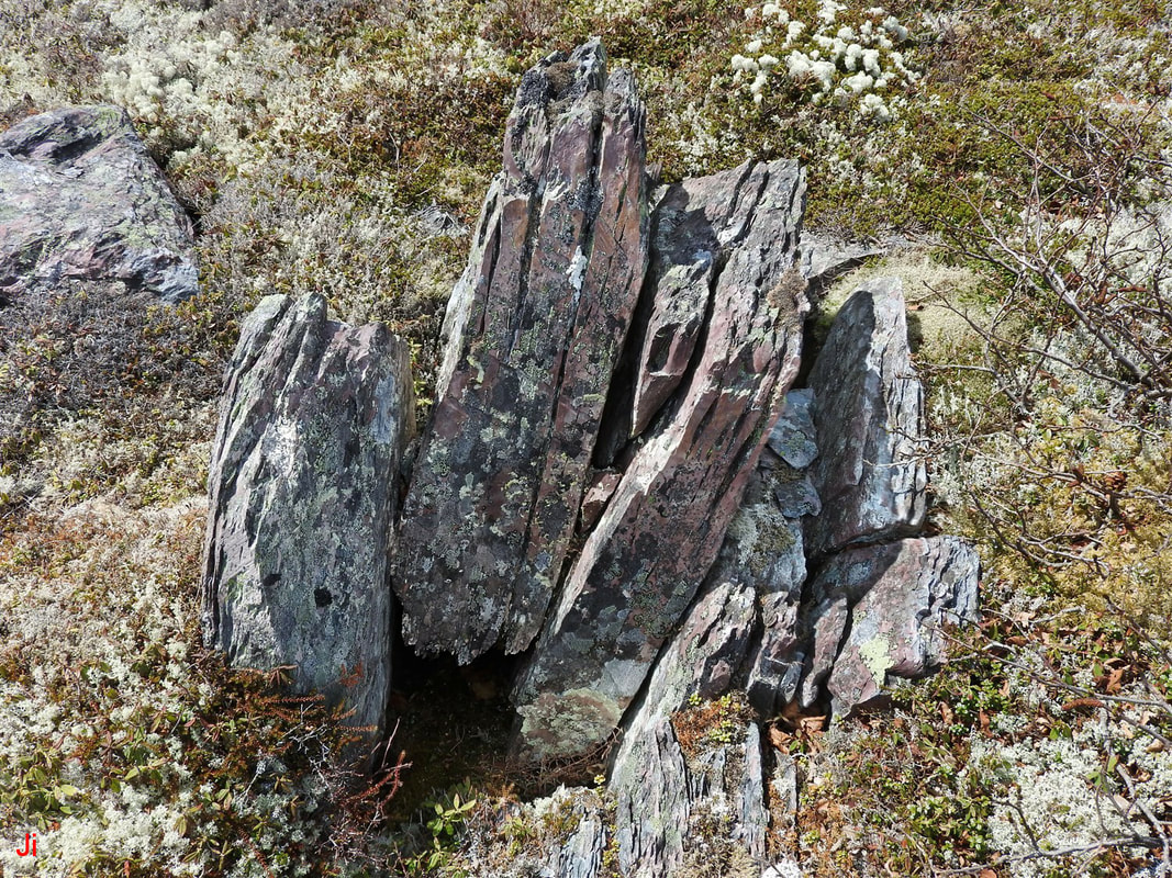
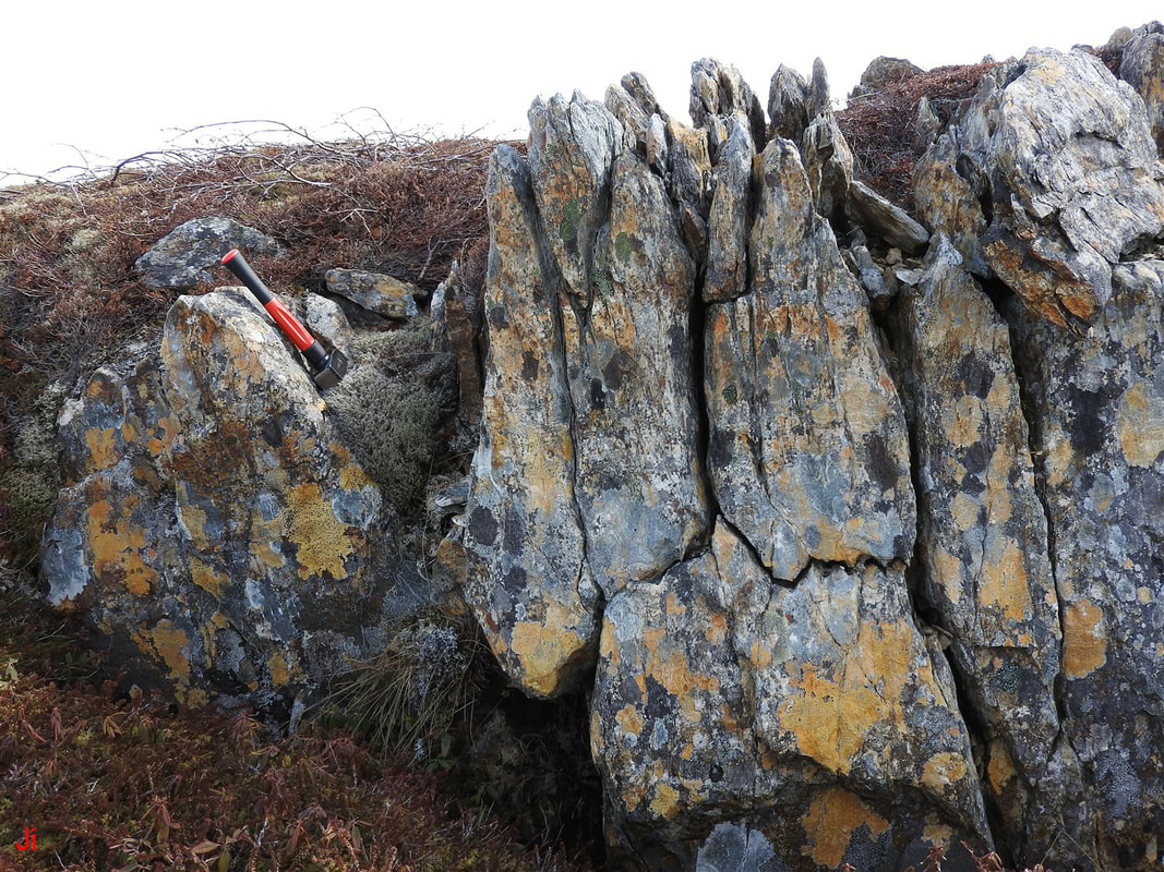
| Heart of Avalonia |
Bedrock erosion by subglacial ice extrusion - Part 02
The process of Bedrock Erosion by Subglacial Ice Extrusion (BESIE, acronym introduced in this section for convenience) is defined and described in Bedrock erosion by subglacial ice extrusion - Part 01, and in Illustrative Feature 09 and in the Second Interim Essay. The present discussion will focus on providing further examples of the process. Understanding bedrock erosion by subglacial ice extrusion is critical to the interpretation of the special geomorphology created by deglaciation of portions of Newfoundland's Avalon Peninsula under cold-based glacial conditions. The grooved patterns formed in foliated bedrock by subglacial extruded ice provide a means for investigating groundwater penetration of frozen bedrock. Two factors, groundwater penetration of frozen bedrock and the stress associated with the deformation of cold glacial ice (cold glaciotectonic action) account all of the ice-disrupted bedrock features described in the Frost-heaved Bedrock Field Observations section of Heart of Avalonia.
Supporting the BESIE model - Part 1
Since it is impractical to conduct centuries-long experiments simulating subglacial conditions on the Avalon Peninsula 12000 years ago, the BESIE interpretation cannot be supported in the usual scientific manner by testing and retesting variations of the process. The recourse adopted here is to provide multiple examples suggesting that the BESIE interpretation is reasonable while simultaneously attempting to argue that competing interpretations are less feasible.
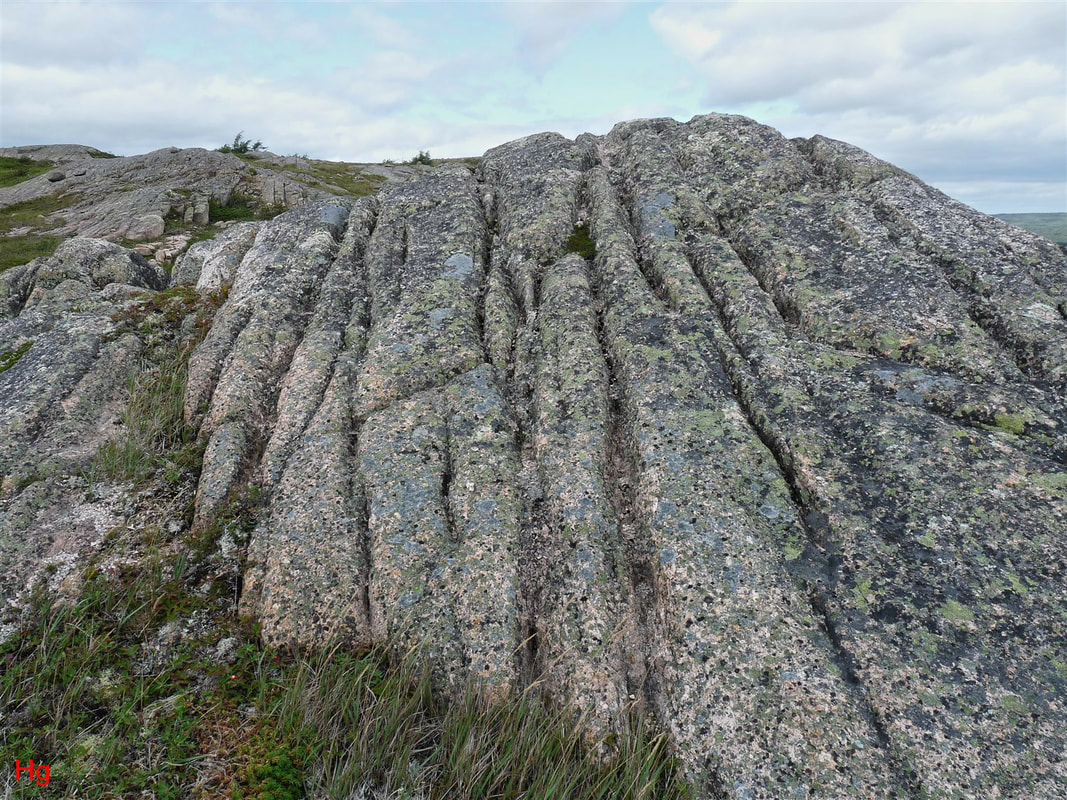
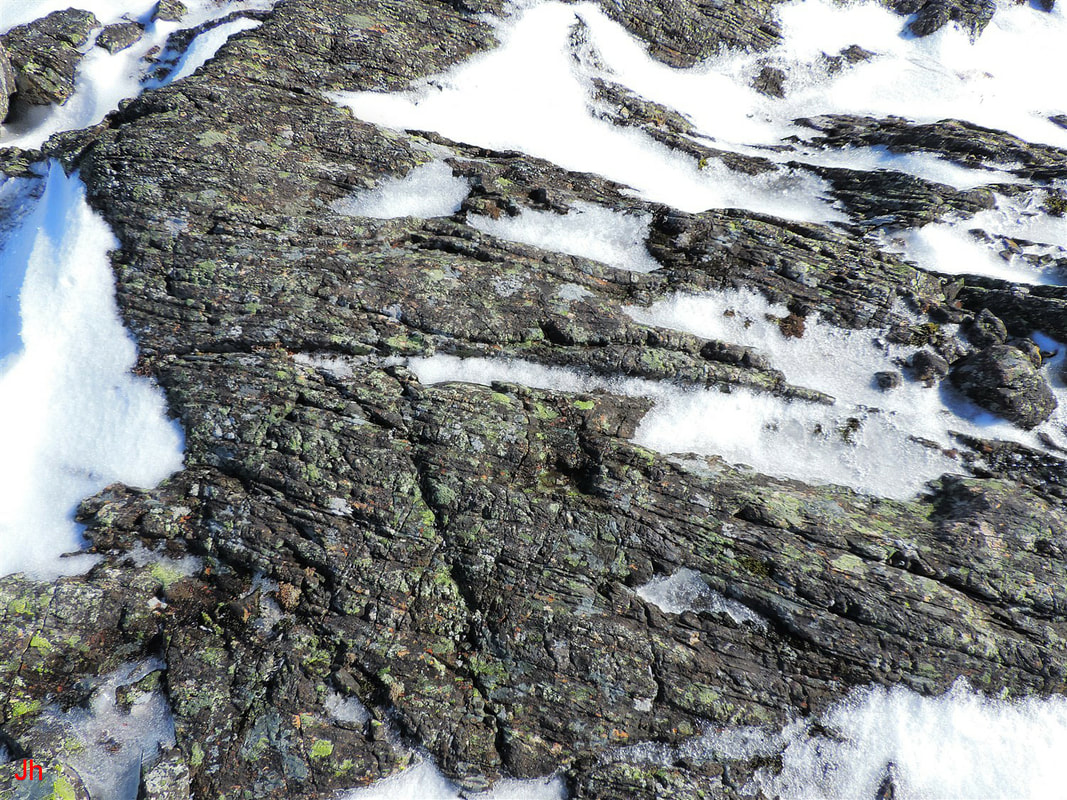
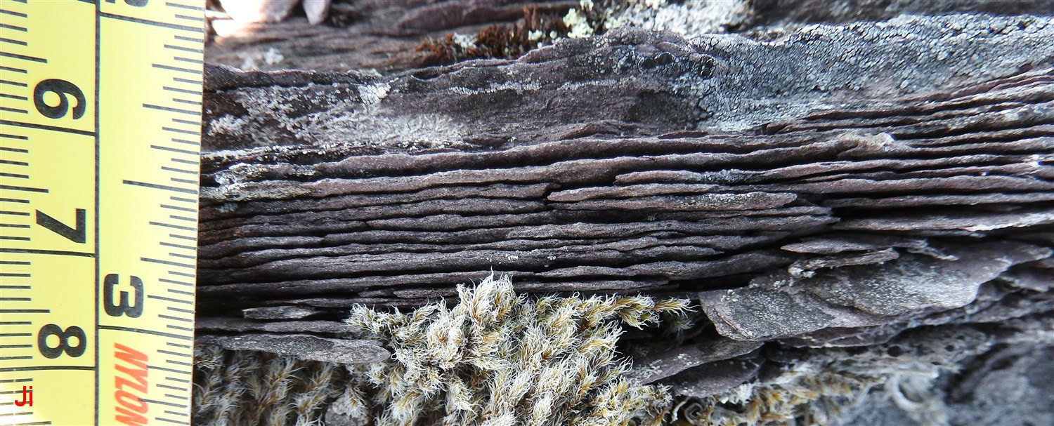
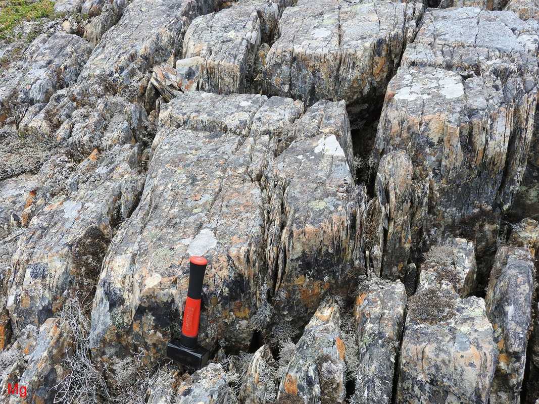
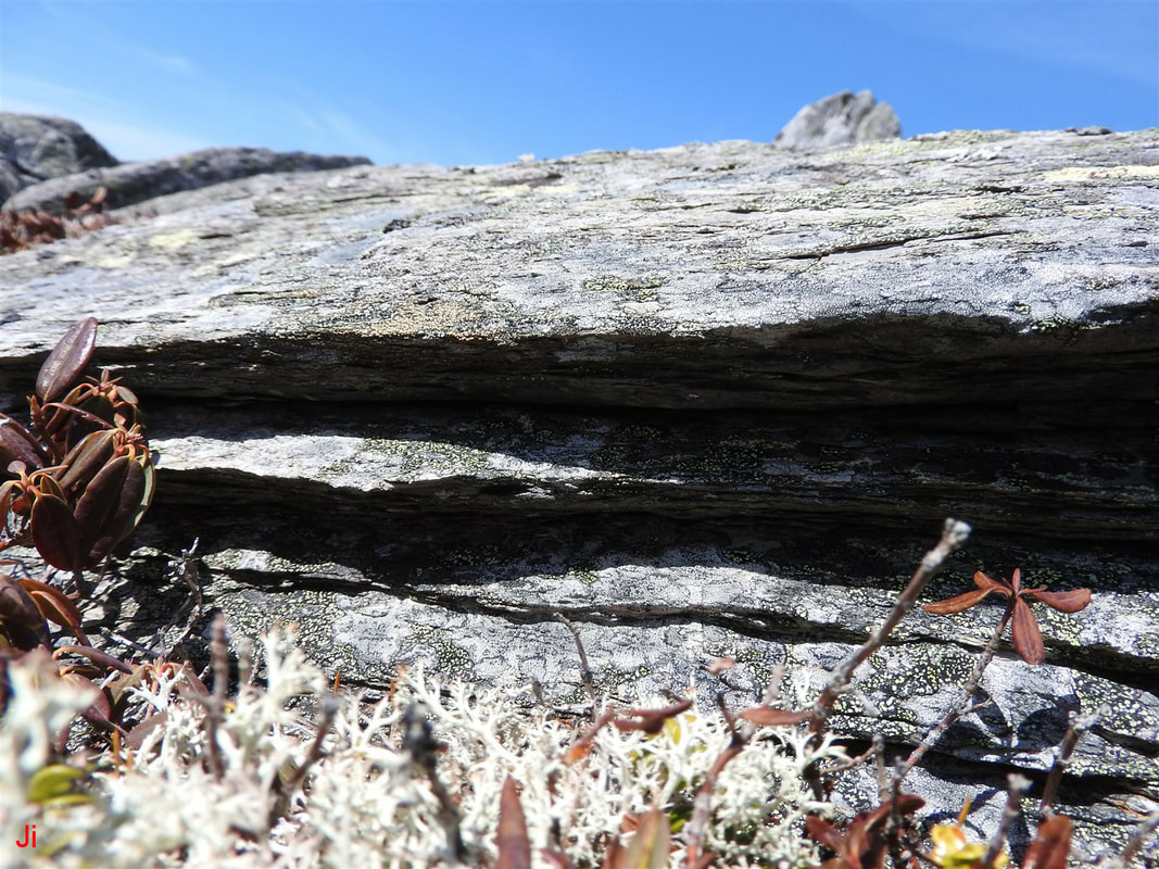
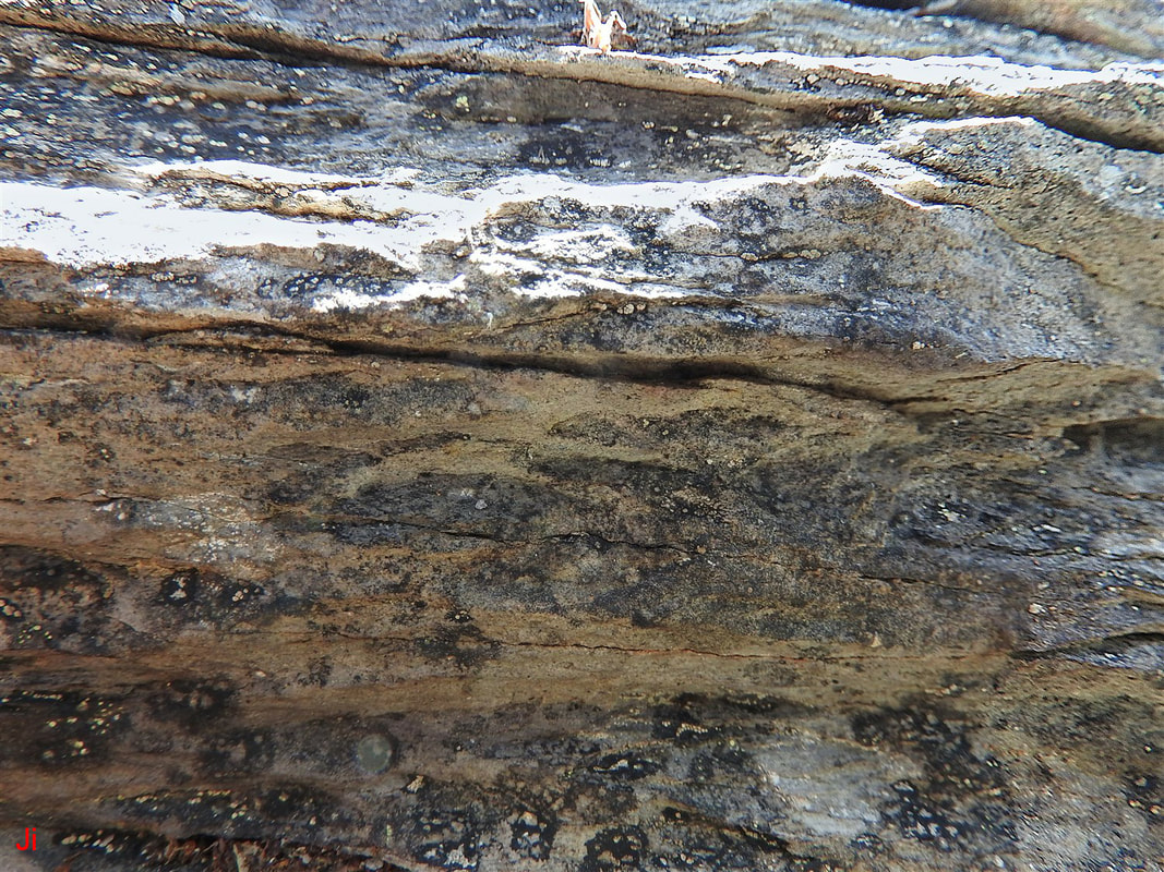
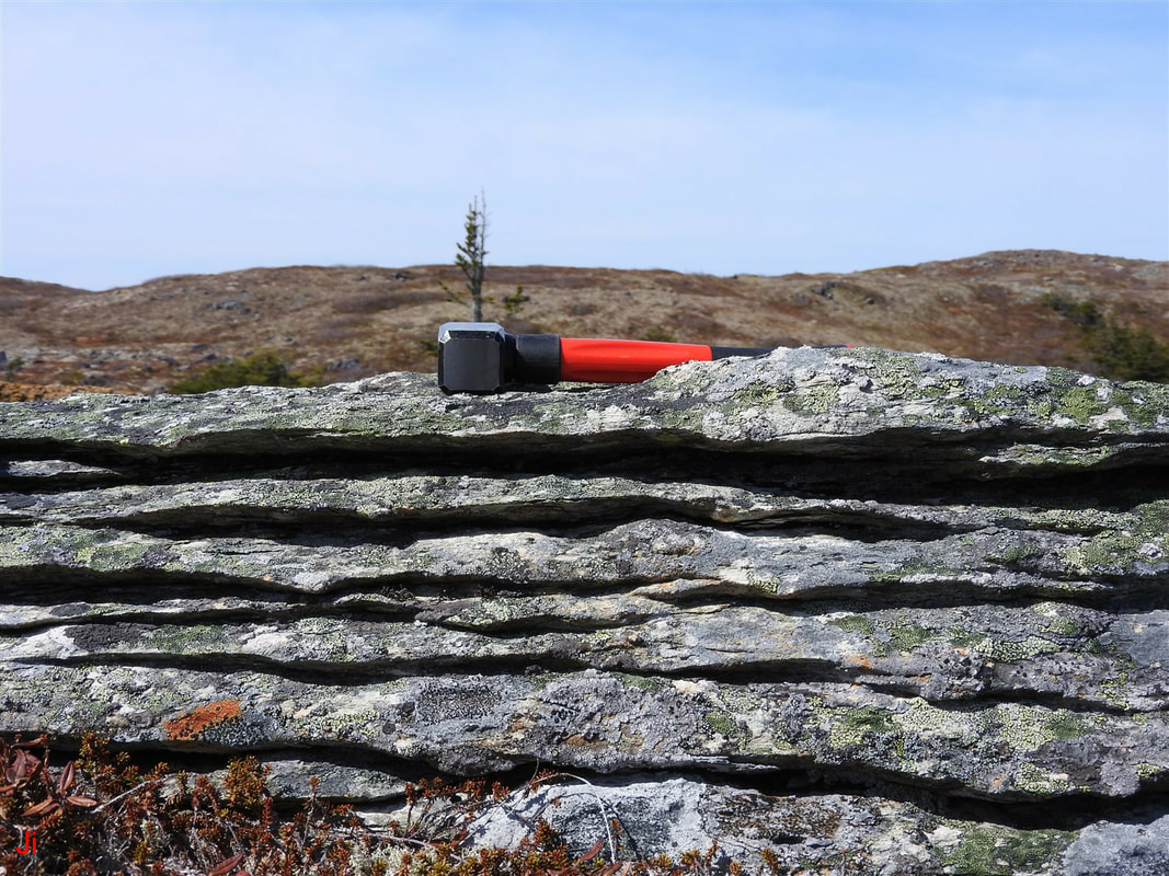
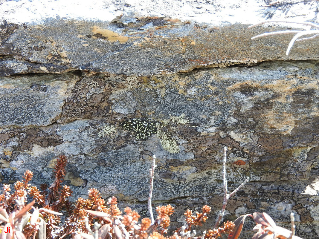
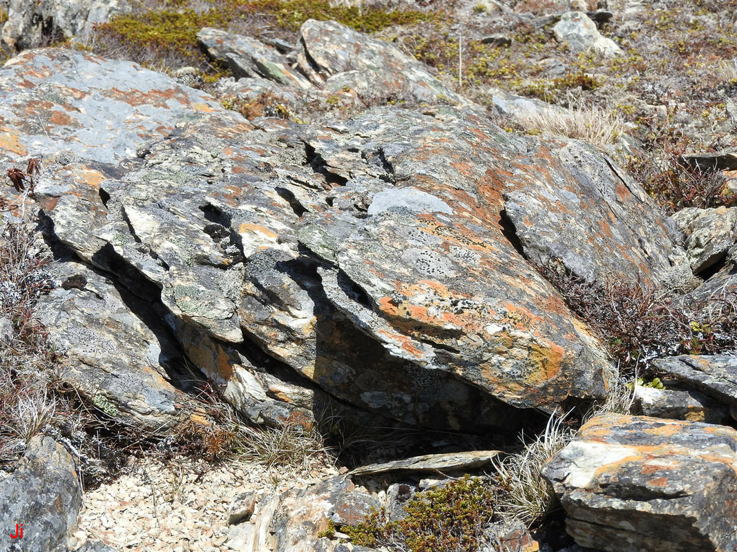
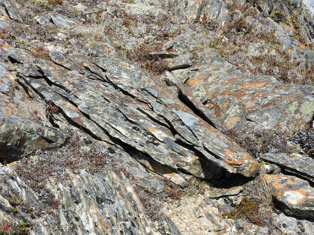
Both of the above photos show repeating grooved patterns in Avalon Peninsula bedrock. Neither pattern was formed by subglacial ice extrusion. The first (left) photo shows granite, apparently eroded by rainwater draining along channels formed by the chemical attack of water on feldspar. Once a channel begins to form, it collects and concentrates rainwater, accelerating erosion and enlarging the channel. The second (right) photo shows grooves formed by the preferential erosion of soft bedding-plane layers in thermally metamorphosed ancient marine shale. The erosion was presumably caused by rainwater and occurred during the Holocene. A complete lack of additional recognizable frost-heave features at both of the locations pictured above helped eliminate BESIE as a potential explanation of the observations. The above illustrations indicate the need to consider alternative interpretations at every location where BESIE is suspected.
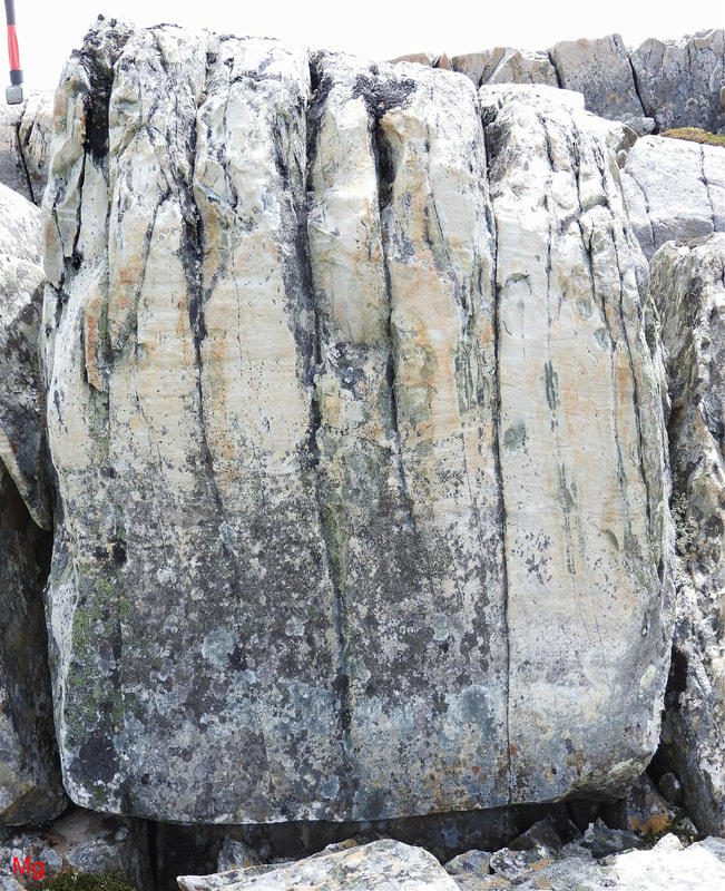
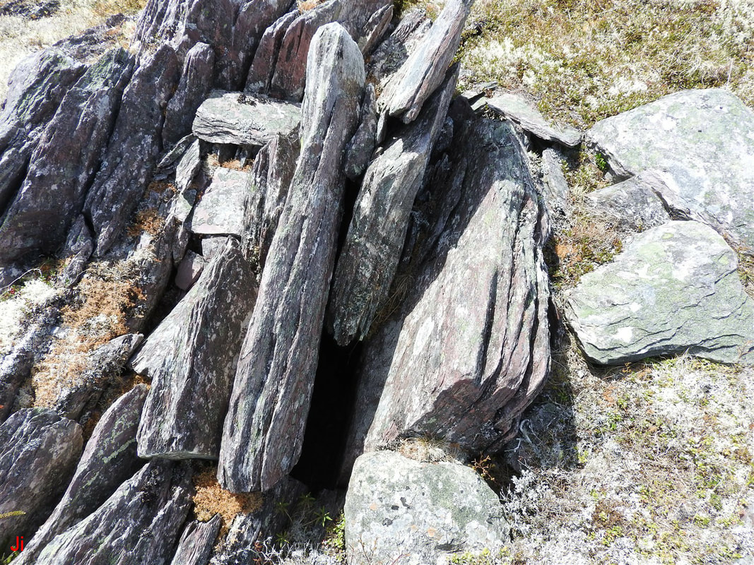
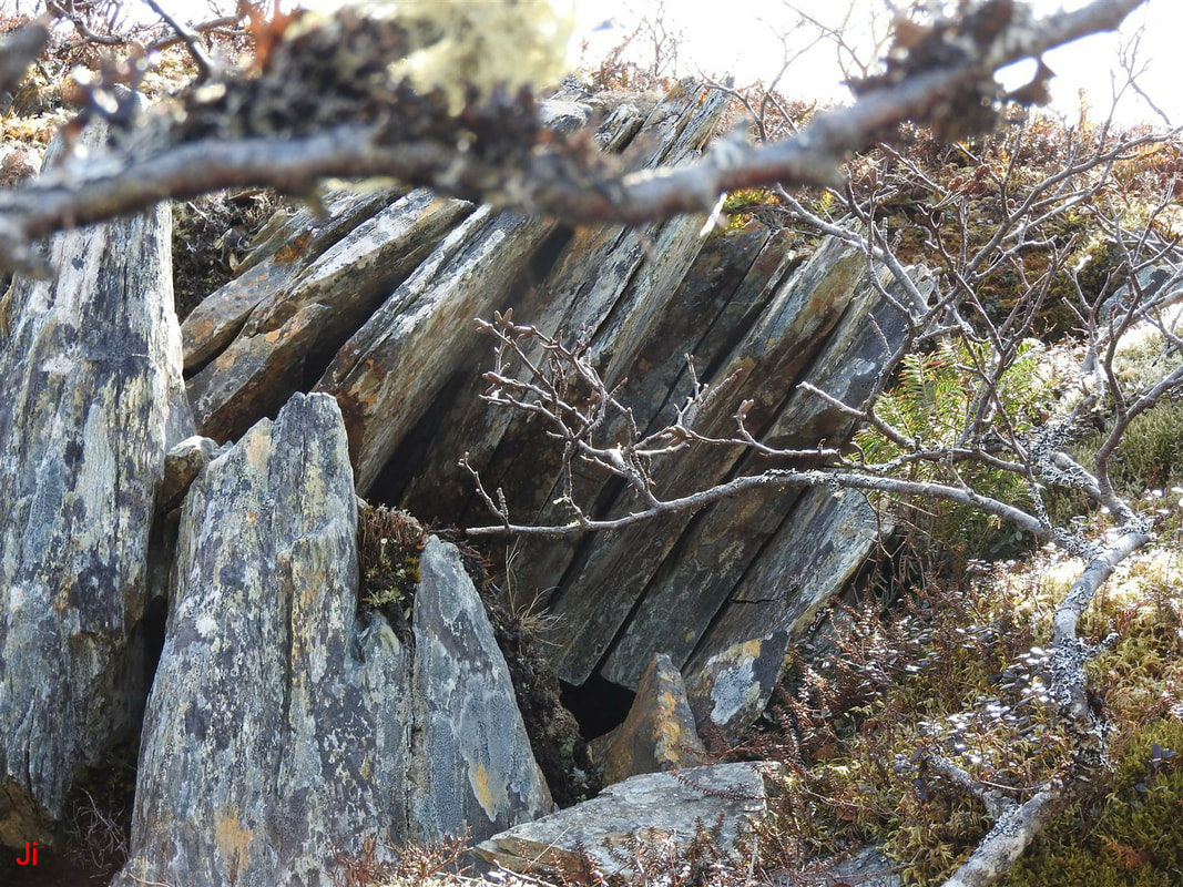
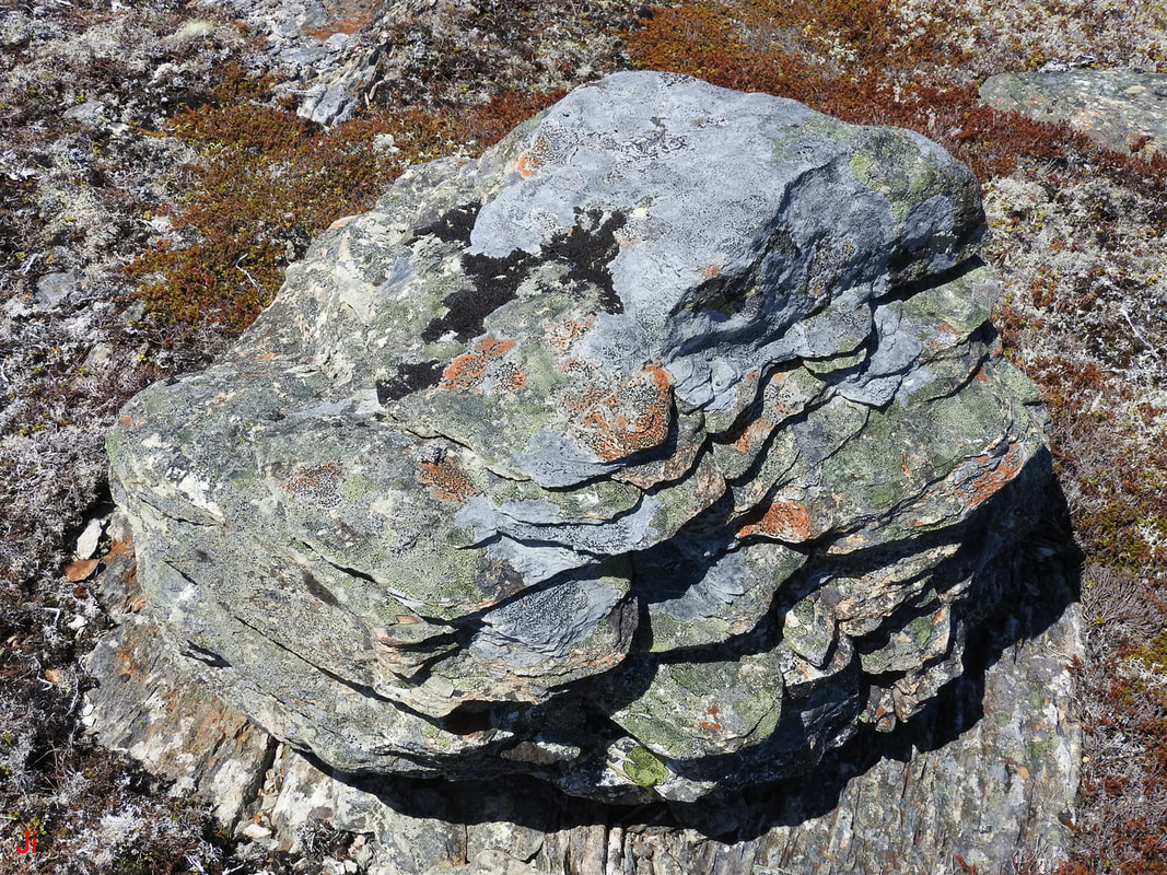
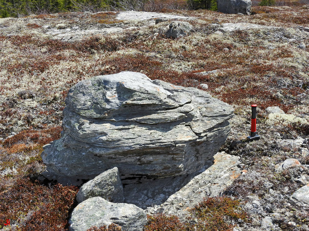
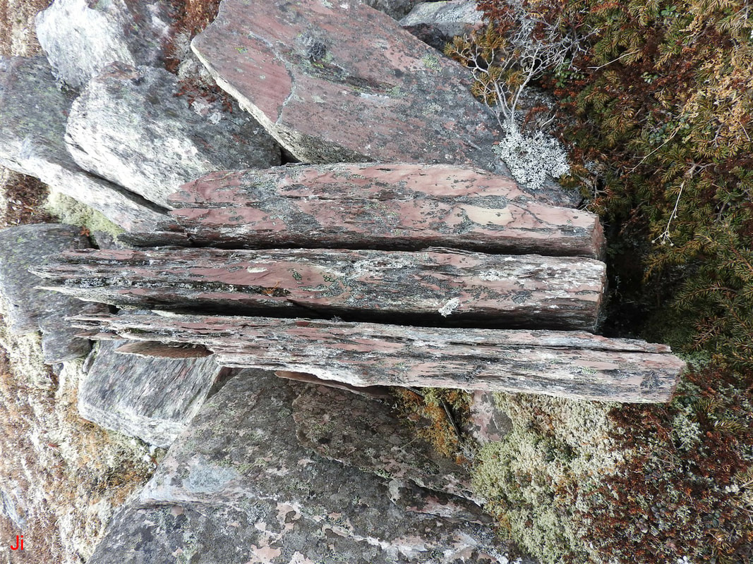
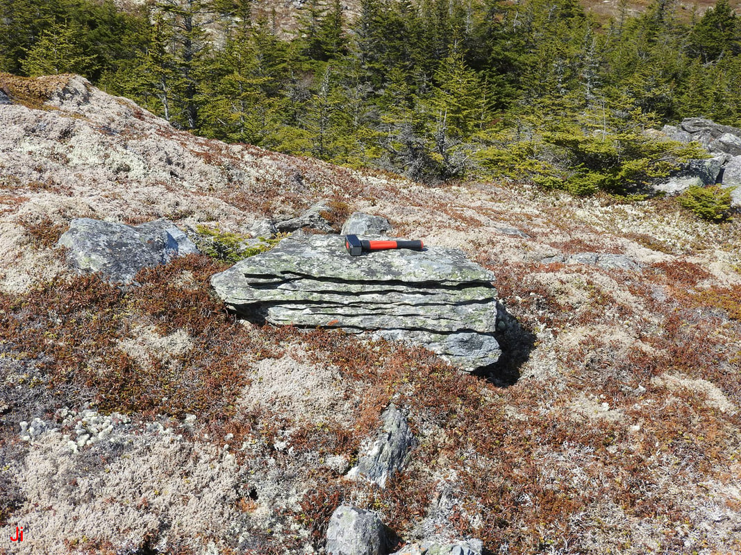
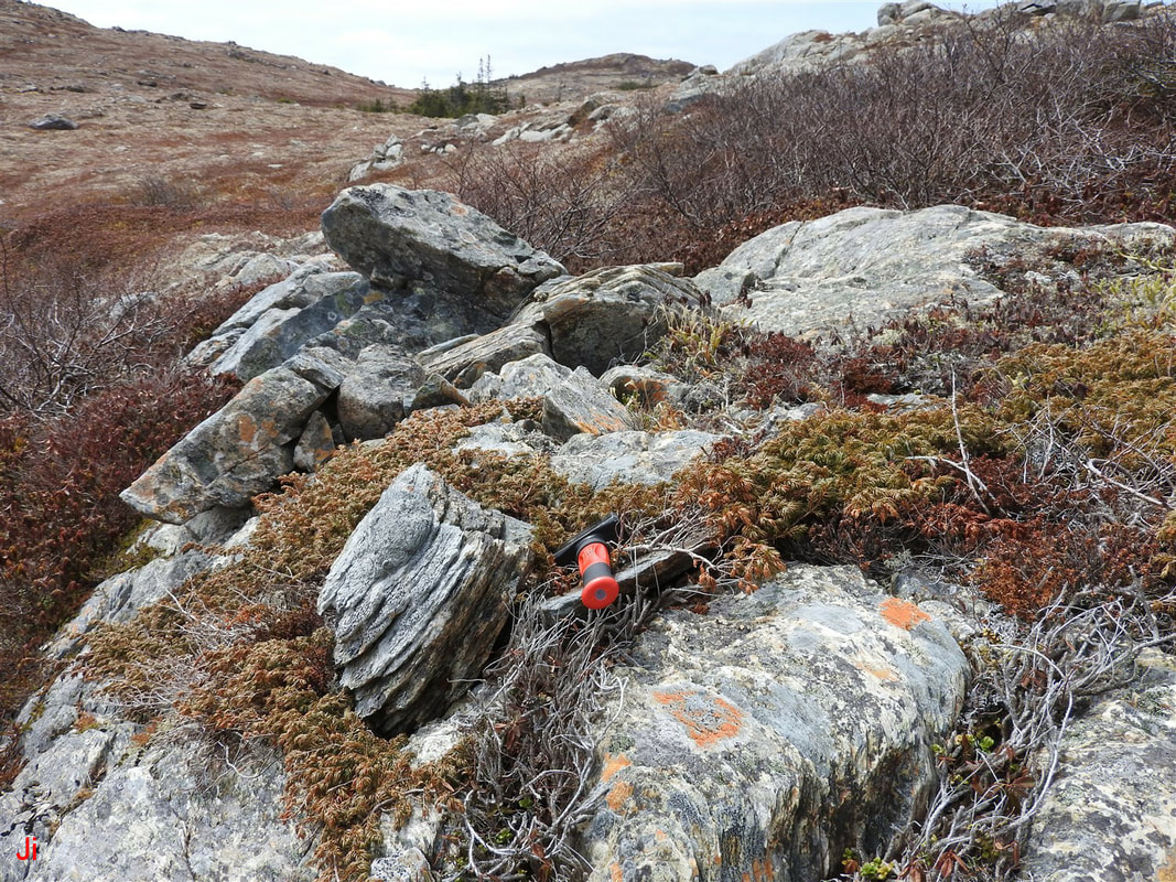
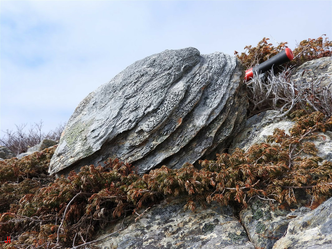
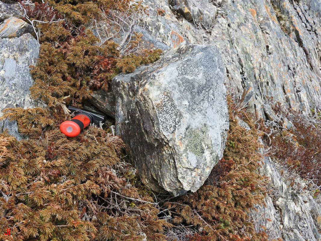
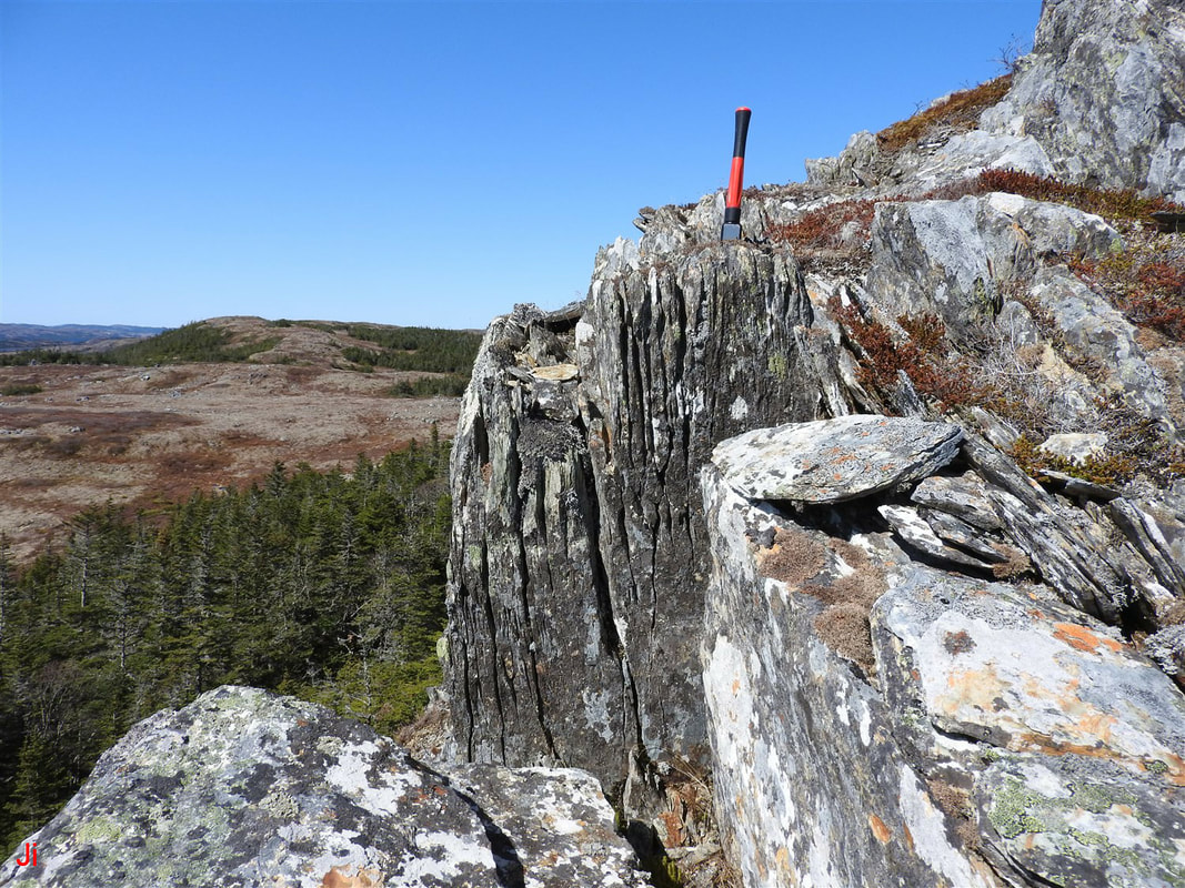
The large block of fine-grained regionally metamorphosed sedimentary rock shown above demonstrates a pattern of grooves typically associated with erosion by subglacial ice extrusion. The grooves follow foliation in the rock, not bedding planes (bedding planes are at right angles to the plane of the grooves). The phyllosilicate-based rock is homogeneous, well indurated and does not appear to be overly vulnerable to chemical attack by water. The block illustrated above has been shifted by subglacial bedrock frost heave and occurs in an area demonstrating widespread, abundant and severe indications of bedrock disruption that occurred beneath cold-based glacial ice cover.
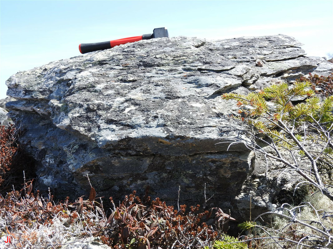
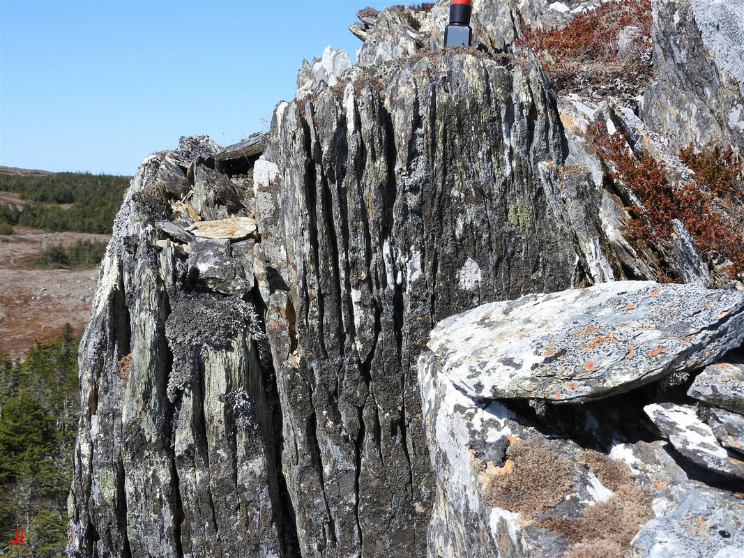
Two important characteristics of erosion by subglacial ice extrusion are visible in the above photo. Firstly, grooves widening upward are prominent. Secondly, the grooves connect to what look like joints extending downward into the block. These joints comprise irregular planes where ice segregation and consequent ice-crystal growth pressure has widened the spacing between layers of foliated phyllosilicate rock. The joints can be interpreted as collector channels, concentrating the feed of pore water or ice toward the grooves.
Although the above-pictured block hints clearly at BESIE being the proper interpretation for the grooves, it is not possible to exclude erosion by Holocene rainwater as an alternative origin. Flowing rainwater could etch channels and could then accumulate and flow in those channels, widening and deepening them. Also, freeze-thaw weathering could augment rainwater erosion or could independently account for some or all of the observed erosion.
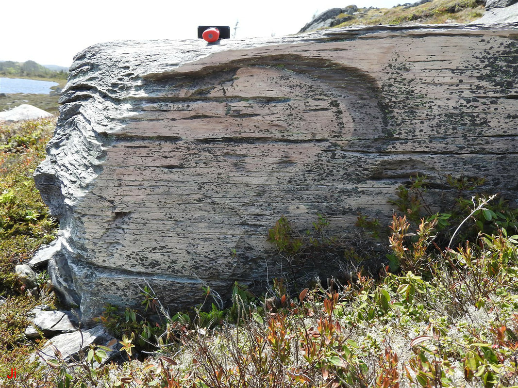
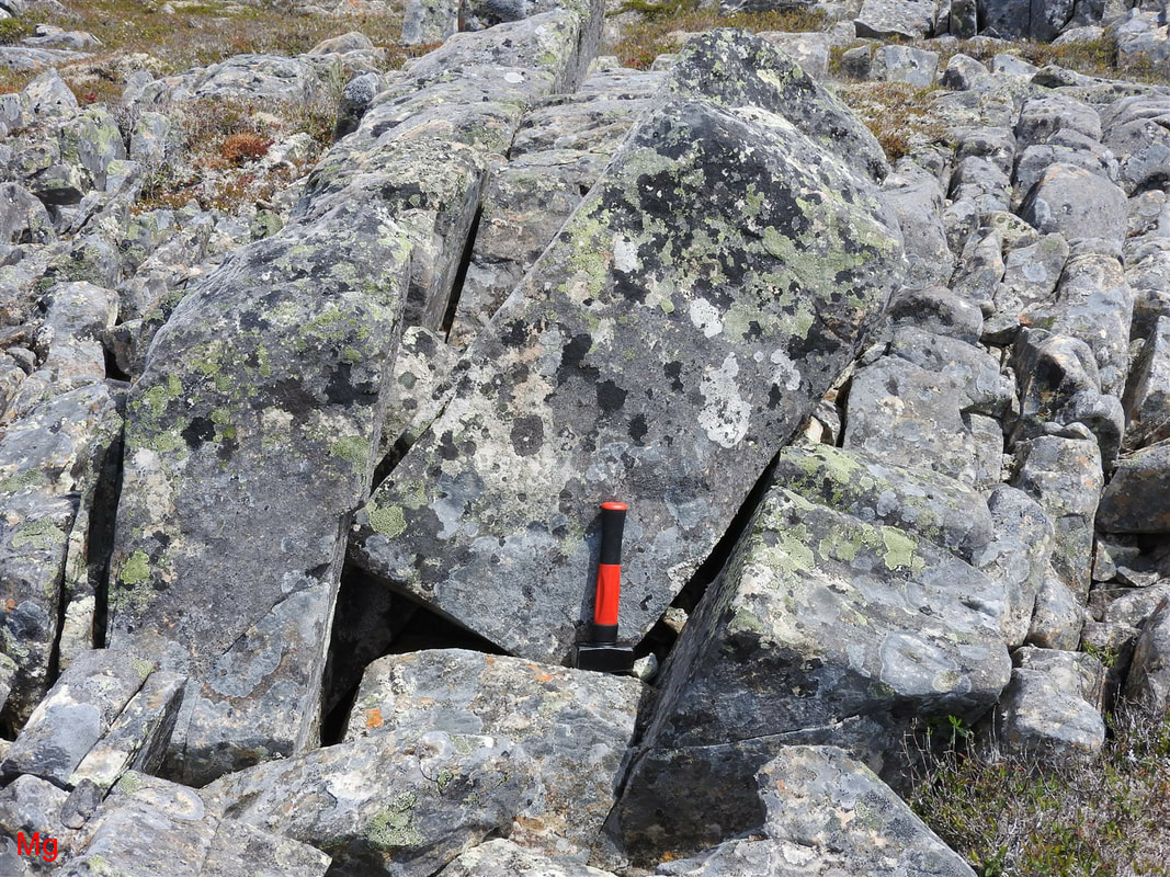
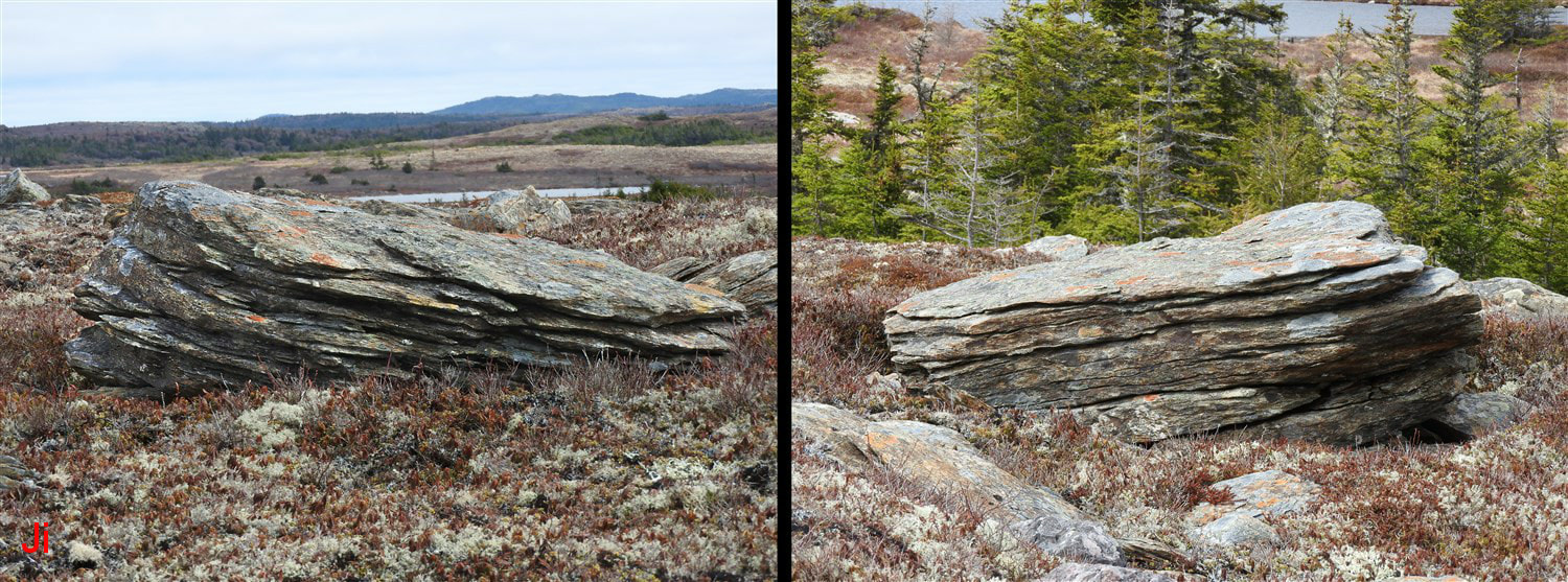
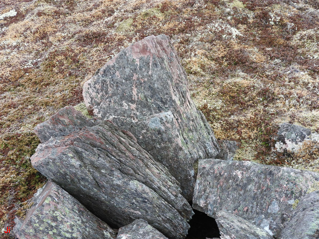
The large block shown above is similar in composition and texture to the block shown previously. The above-pictured block has rotated 90 degrees about a horizontal axis to assume its present orientation. Foliation in nearby bedrock dips approximately vertically. If a non-BESIE interpretation for the grooves seen on the left-facing surface of the block were to be adopted, an explanation for the relative lack of grooves on the side of the block facing the camera would be needed. The block appears to be a glacially-shifted frost-heaved joint block. The foliated block shows evidence of partial delamination along planes of foliation. Within the BESIE model, this apparent delamination would reflect channels, widened by ice segregation, that collected ice or pore water and directed it toward the grooves.
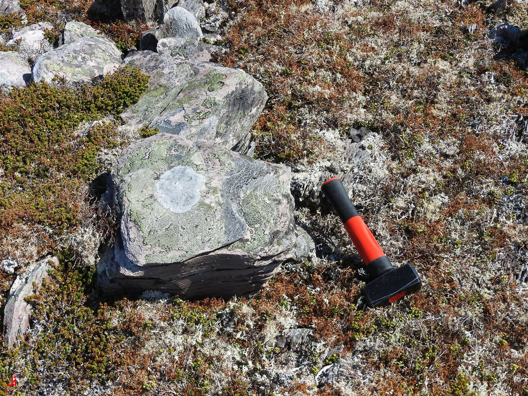
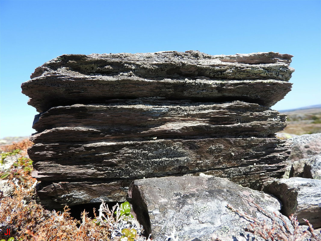
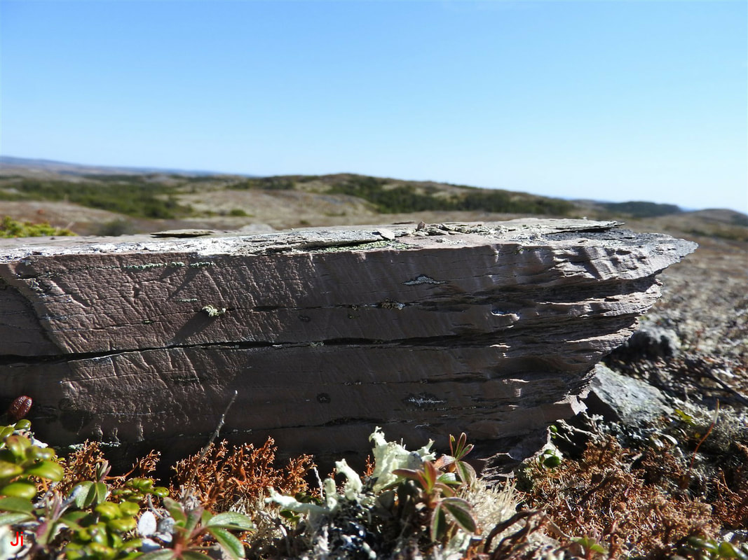
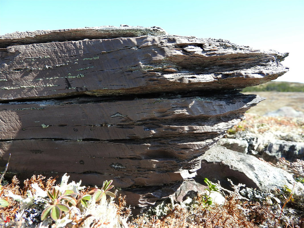
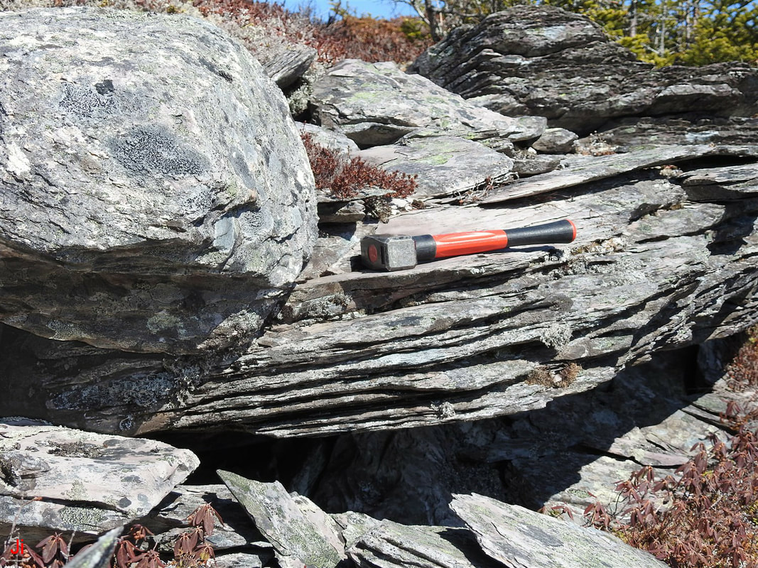
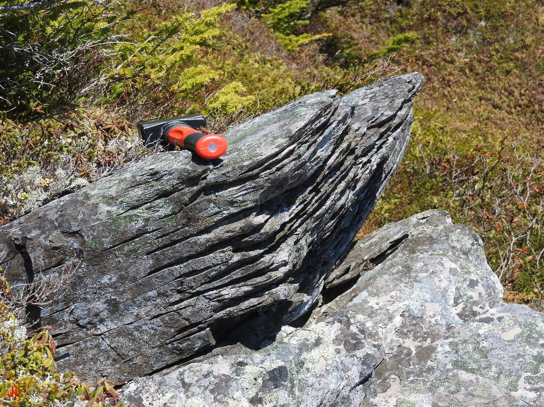
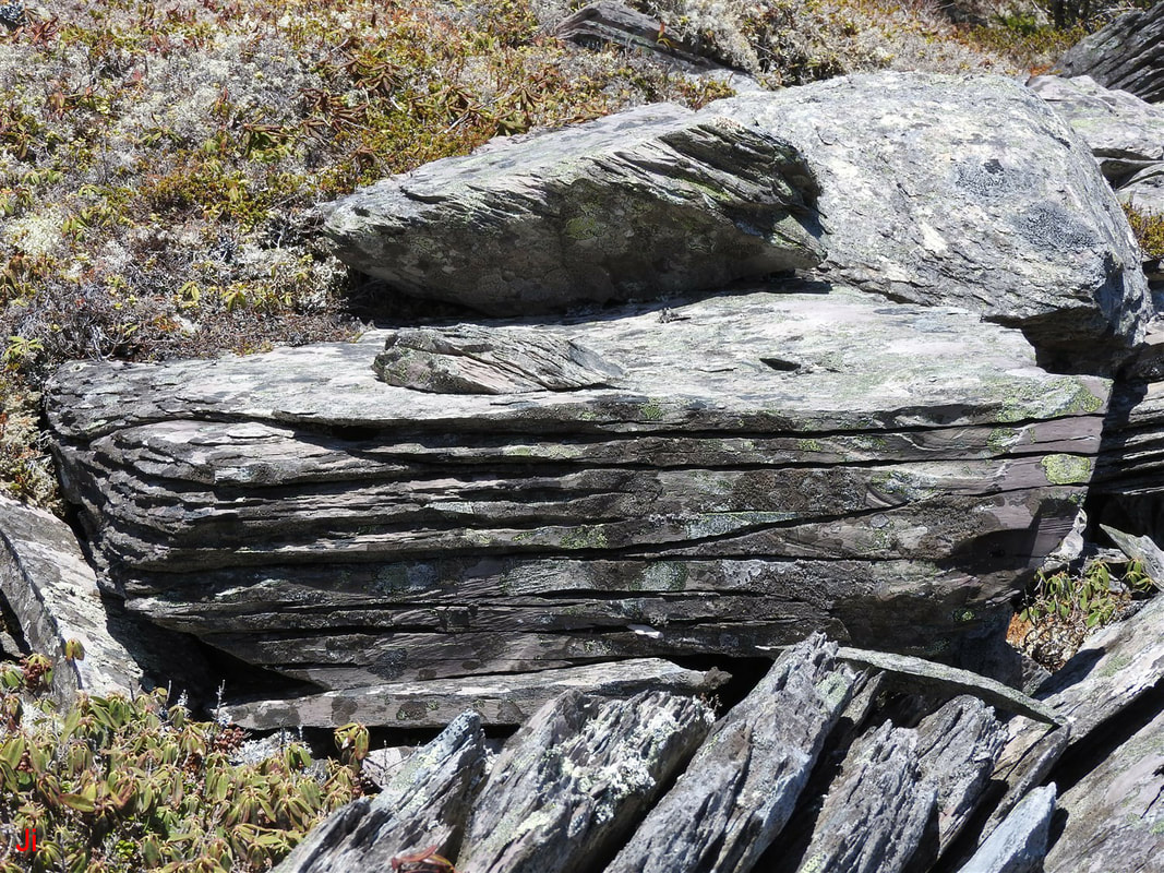
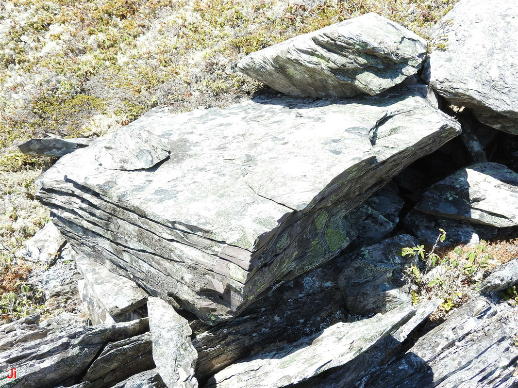
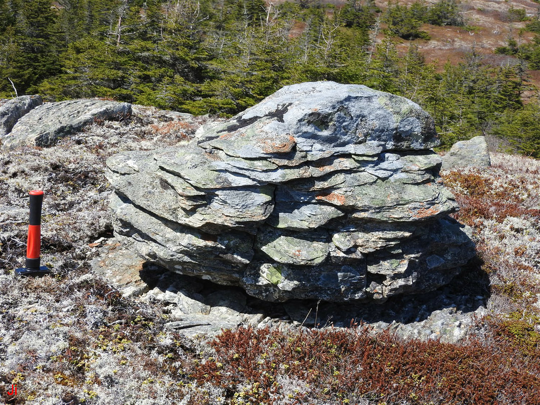
The small, glacially-transported block seen to the left of the hammer in the above photo shows an asymmetric pattern of grooves on its side surfaces. Grooves are most pronounced on the side of the block facing the hammer. For purposes of the following discussion, let the side surface facing the hammer be designated as surface "1" and the side surface facing the camera be designated as surface "2". The three photos below contrast the grooves appearing on surface "1" (first photo below) with the grooves appearing on surface "2" (second and third photos below).
The above photos show a pattern of grooved surfaces that is typical of the pattern commonly observed on frost-heaved joint blocks interpreted to have been affected by subglacial ice extrusion. The surface designated previously as surface "1" is the original top surface of the joint block before the block became dislodged from bedrock and was subsequently glacially transported and rotated 90 degrees about a horizontal axis. Note the micro-scale delamination of rock within the grooves. This micro-scale delamination hints at the mechanism by which the grooves were formed. The grooves were apparently formed by a large number of small-scale frost heave events whereby slivers of rock were separated from the block by ice-crystal growth pressure and by shear stress accompanying the deformation of segregated ice as the segregated ice was extruded into an overlying glacier (see BESIE model: Formation of grooved erosion surfaces , below, and Bedrock erosion by subglacial ice extrusion - Part 01).
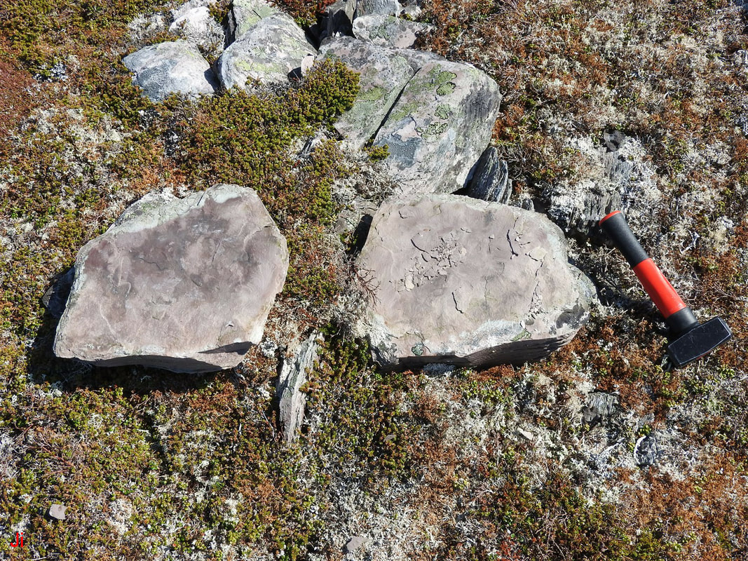
The block shown above possesses an especially prominent ice-widened joint appearing about half way down from the top as seen in the second two photos. The block was tested to determine if complete failure on this joint had occurred, thereby separating the block into two loose pieces. The block was determined to be intact and not easily broken. This observation implies that the prominent joint was not likely widened by Holocene freeze-thaw weathering since the rock was brittle and would not tolerate the flexure needed to widen a joint without fracturing the small block completely. After confirming the mechanical integrity of the block, the piece was hammered until it fractured along the central joint. The pieces were separated and are shown below.
The block shown above possesses an especially prominent ice-widened joint appearing about half way down from the top as seen in the second two photos. The block was tested to determine if complete failure on this joint had occurred, thereby separating the block into two loose pieces. The block was determined to be intact and not easily broken. This observation implies that the prominent joint was not likely widened by Holocene freeze-thaw weathering since the rock was brittle and would not tolerate the flexure needed to widen a joint without fracturing the small block completely. After confirming the mechanical integrity of the block, the piece was hammered until it fractured along the central joint. The pieces were separated and are shown below.
Note the thin fragments of rock visible on the right-hand section of the block (bottom section before fracturing and separating the pieces). While the texture of the foliated fine-grained sedimentary rock could be described as slatey, the rock will not generally delaminate when hammered, except along pre-existing visible joints. Rather, the rock typically breaks randomly and irregularly, across the plane of foliation. The delamination evidenced by the fragments seen above appears most likely to have been induced by the action of groundwater or ice penetrating the rock at a time prior to deglaciation and frost heave, while the block was still embedded in bedrock.
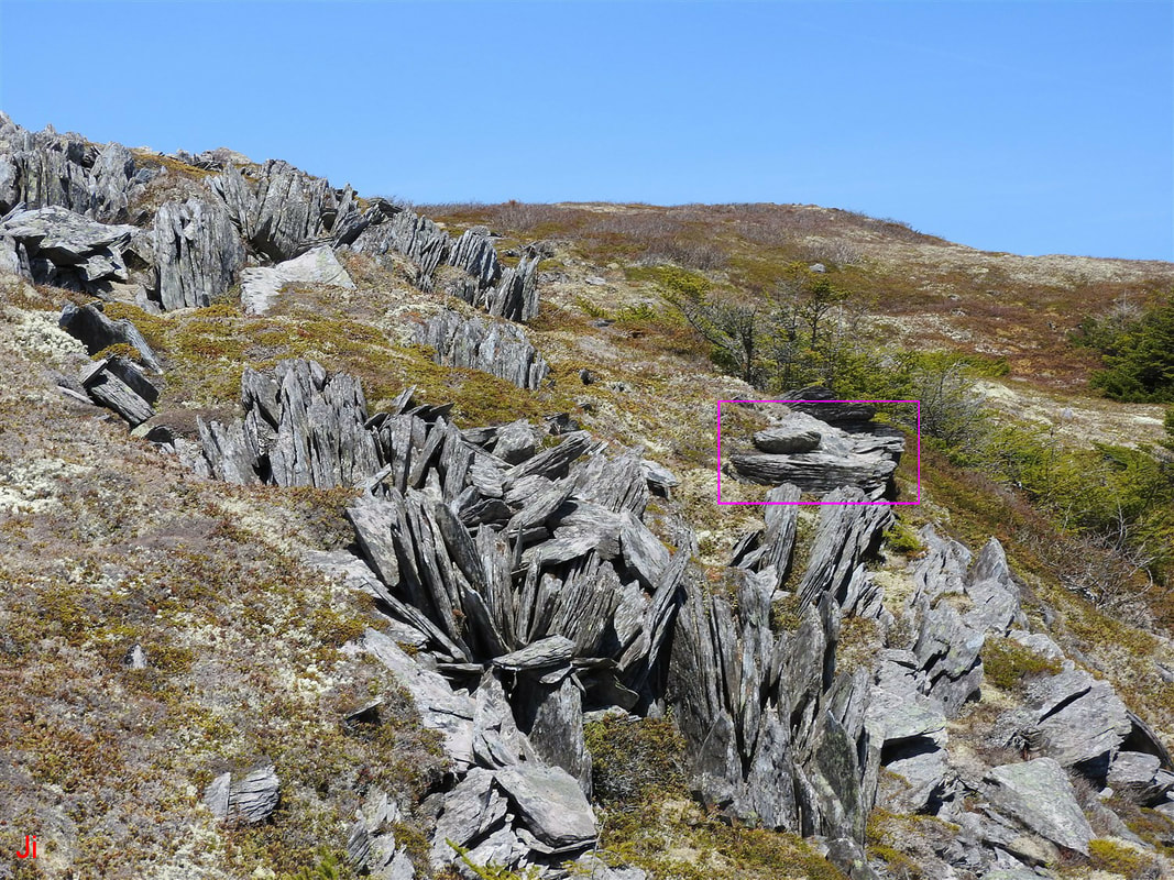
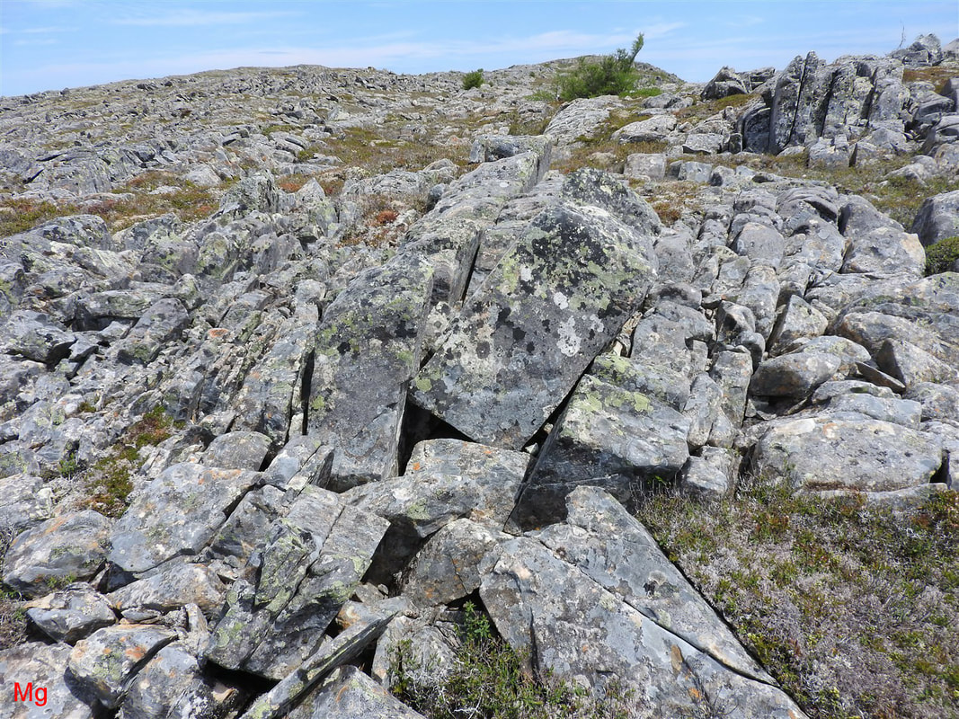
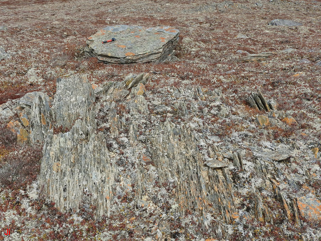
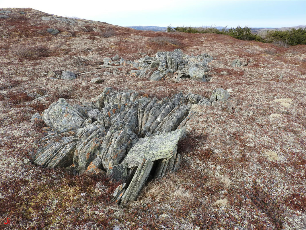
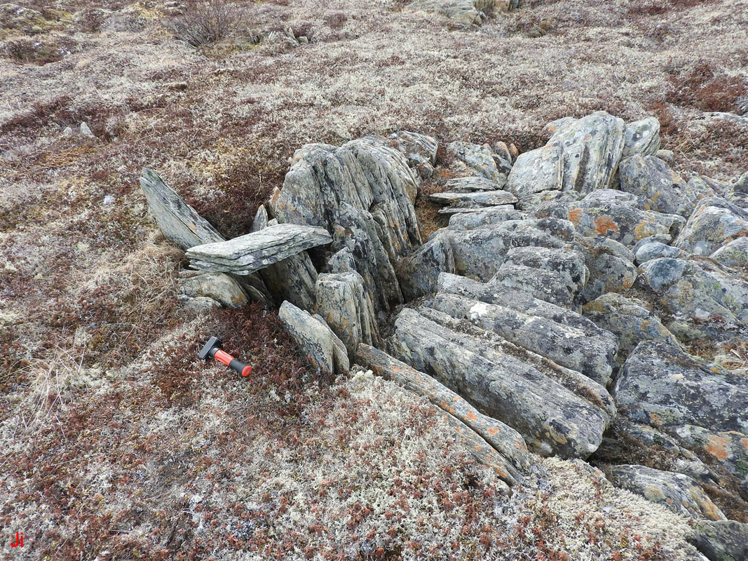
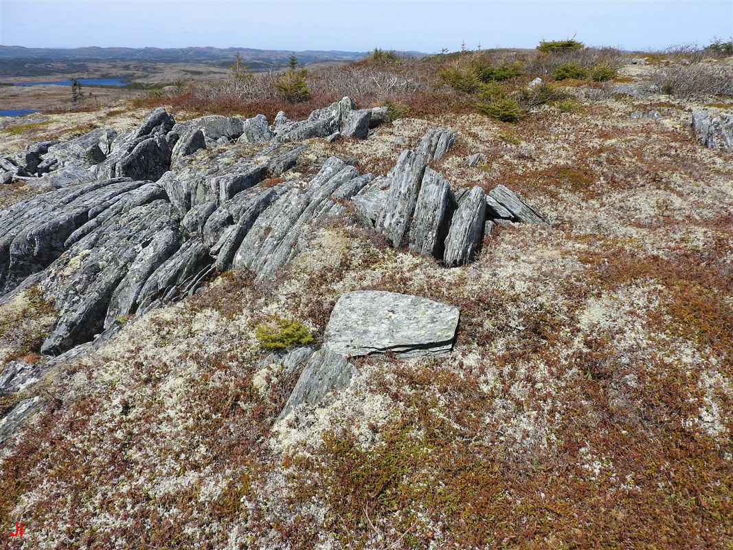
The above photo shows an area of ice-disrupted bedrock demonstrating the grooved patterns characteristic of subglacial ice extrusion. The grooved patterns tend to face primarily upward on blocks that remain rooted in bedrock. Upward-facing grooves are expected in instances of erosion by subglacial ice extrusion, but upward-facing grooves might also reflect the action of rain or other Holocene weathering processes acting preferentially on the top surfaces of exposed blocks. The blocks outlined by the magenta rectangle above have been dislodged completely from bedrock and have rotated approximately 90 degrees about a horizontal axis. Any grooves eroded into these blocks would not reflect top vs. bottom asymmetry, unless the erosion occurred while the blocks were still erect. A potential exception could result when considering the possible effect of prevailing winds or the effect of differing levels of average sunlight illuminating the side surfaces of the blocks. Effects like these could cause asymmetry in the degree of erosion experienced on sides of a block facing in different compass directions.
The above photo shows a zoomed-in view of the blocks shown previously in the magenta rectangle. The foreground in the photo shows frost-heaved and delaminated bedrock that has been rotated top-rightward. The consistency of this rotation trend, extending over several nearby blocks, implies the action of deformational flow in an overlying glacier. The blocks in the background show asymmetric patterns of grooves on their sides, but the more strongly grooved surfaces face in differing compass directions on three nearby blocks. This observation militates against an argument that the asymmetry in the pattern of grooves is the result of asymmetries in present-day wind or sun exposure.
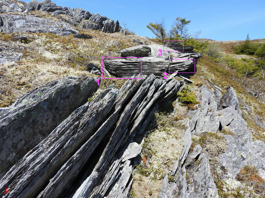
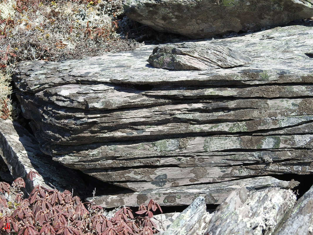
The numbering on the above photos corresponds to the numbering of the magenta rectangles shown on the preceding photo. The grooves on blocks (1) and (2) face outward in approximately opposite directions. The grooves in block (3) face outward in a direction similar to block (2) but are angled about 30 degrees toward the camera. The blocks demonstrate the pattern of grooves tapering inward to joints that characterizes erosion by subglacial ice extrusion. It is reasonable to assume that all three blocks are frost-heaved joint blocks. The blocks apparently rotated in different directions after being dislodged from bedrock substrate. Additional closeup photos of block (1) appear below.
The first (left) photo above shows what was presumably the original (before frost heave) side of the block. The second (right) photo above shows a corner of the block, with the original bottom (before frost heave) of the block seen to the right of the corner.
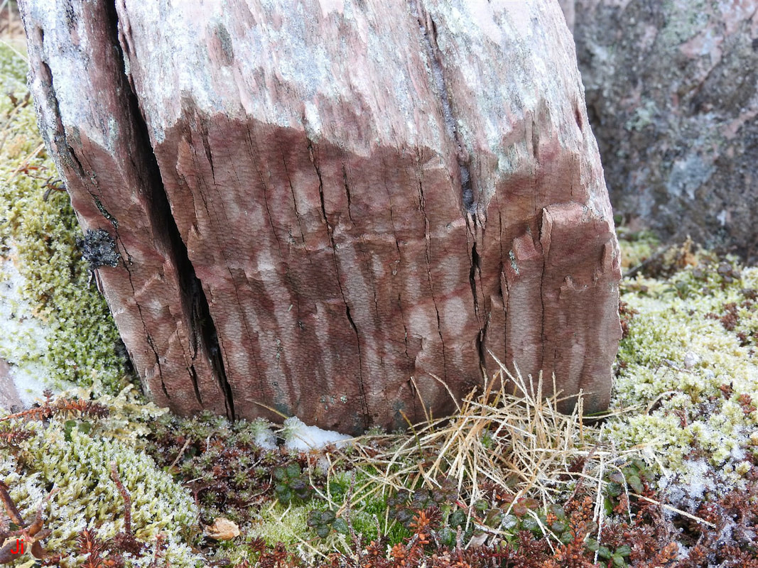
The two closeup photos shown above contrast the grooved (presumably original top) surface of the dislodged and rotated frost-heaved joint block with the relatively smooth (presumably original bottom) surface of the same block. Contrasting opposing surfaces, like those seen in the above photos, provide convincing evidence that most of the erosion visible on the block occurred before the block tipped over. Given that the blocks tipped over before the Holocene began, then the erosion features on the blocks are of subglacial origin.
BESIE model: Formation of grooved erosion surfaces
A discussion of modes of formation of grooved erosion surfaces within the BESIE model, with diagrams, is given in Bedrock erosion by subglacial ice extrusion - Part 01. The discussion below presents additional field observations supporting the BESIE model of groove formation. The observations presented below imply a further generalization that a continuum exists between the formation of grooves by ice extrusion and the subglacial formation of bedrock frost heave monoliths. Within this interpretation, groove formation becomes, in essence, micro-scale subglacial bedrock frost heave.
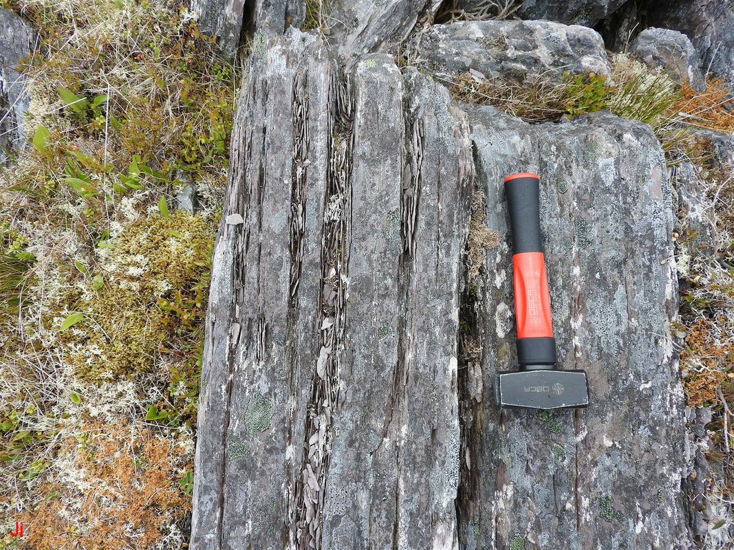
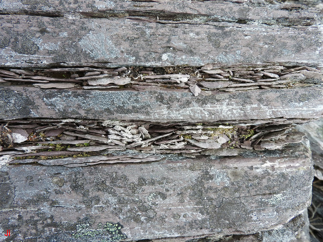
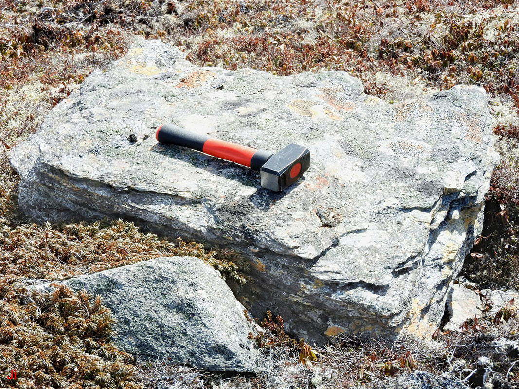
A frost-heaved joint block with grooves eroded into its top surface is shown in the above photo. While the groove seen just to the left of the hammer is empty and the next groove to the left is partially empty, other grooves are occupied by small slivers of delaminated rock. This example can be interpreted as an instance of erosion by subglacial ice extrusion where grooves were formed but were left in a partial state of completion. Within this interpretation, the grooves are seen as resulting from a micro frost-heave process whereby ice-crystal growth pressure and shear stress imparted by extruded ice delaminate the rock and dislodge the resulting fragments. In most cases, the dislodged fragments are carried away by the deformational flow of overlying glacial ice or by the action of wind and rain post deglaciation. The full removal of dislodged fragments leaves behind empty grooves. A closeup of the above-pictured block, highlighting grooves that are still occupied with frost-wedged fragments, is shown below.
Given the hypothesis that the small fragments of rock seen in the above photo were formed in a subglacial process 12000 years ago, it is reasonable to question whether such small fragments could survive until the present day without completely disintegrating and vanishing. The survival of the fragments requires an exceptional degree of resistance of the host rock to Holocene erosion processes. There are other independent indications that the host rock is highly resilient. Sharp corners observed on blocks fractured and separated by glacial action suggest low rates of Holocene erosion. Quartz veins crossing glacially polished bedrock surfaces are often seen to remain flush with the surface, indicating that the host rock erodes no faster than quartz. The exceptional degree of resistance to Holocene erosion of some of the major rock groups hosting bedrock frost heave features on the Avalon Peninsula undoubtedly helps account for the excellent preservation of many frost-heave artifacts.
The micro frost-heave process described above can be observed at many locations in several geometries and in different kinds of foliated rock. Some examples are provided below.
The micro frost-heave process described above can be observed at many locations in several geometries and in different kinds of foliated rock. Some examples are provided below.
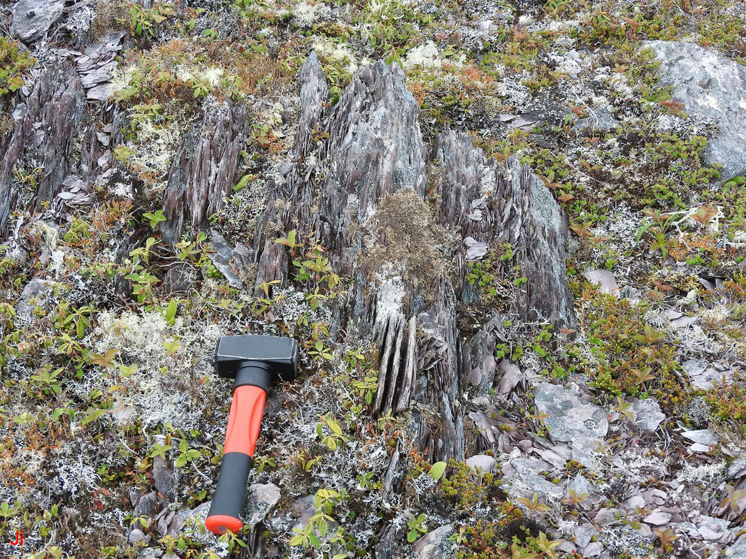
Three small, separated fragments of frost-heaved bedrock can be seen to the right of the hammer in the above photo. The host bedrock outcrop is intensely delaminated on many scales, with frequent (although hard to see without close inspection) instances of micro-scale frost heave. The pictured bedrock outcrop has presumably been eroded by subglacial ice extrusion.
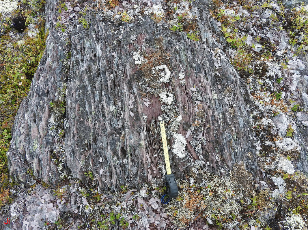
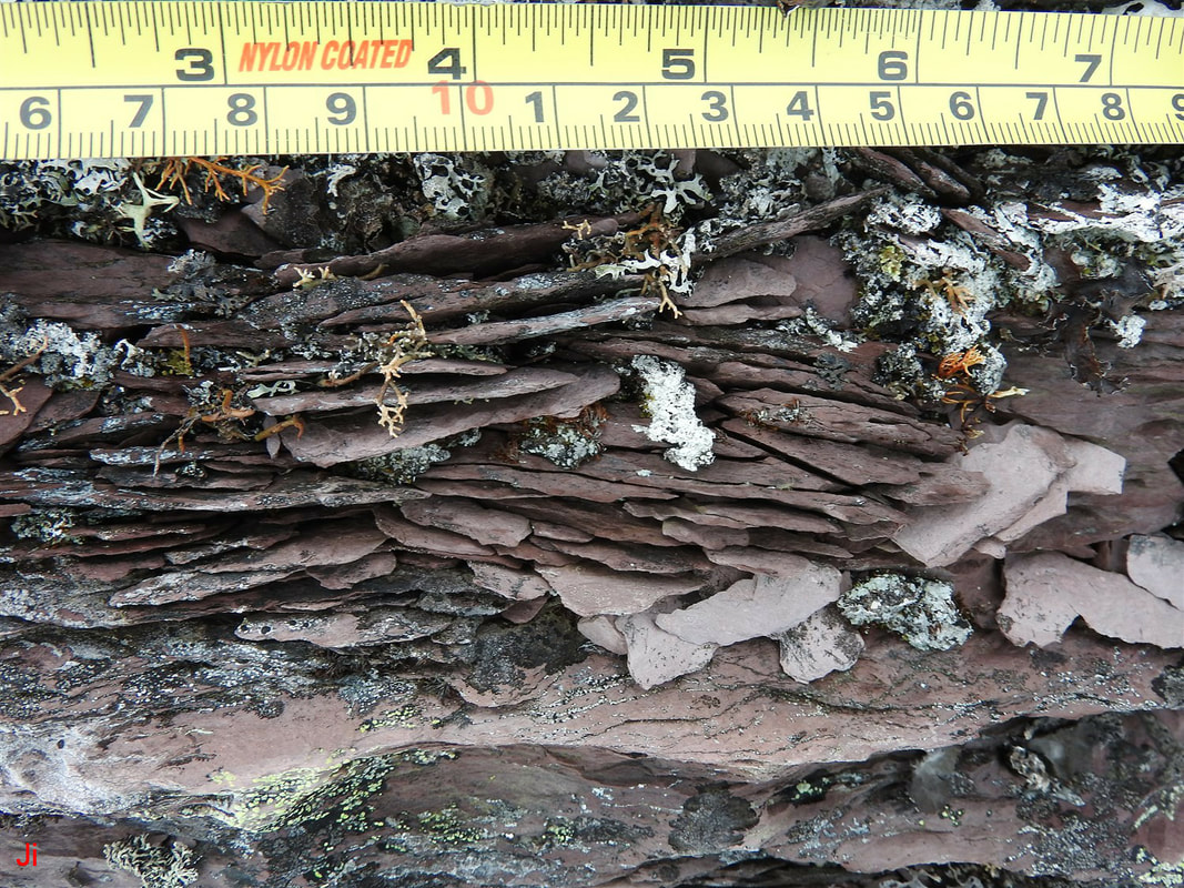
Another bedrock outcrop affected by subglacial ice extrusion is shown above. Note the micro-scale delamination of the rock visible just to the left of the tape measure. A closeup of this feature is shown below.
Undoubtedly, Holocene erosion, including the effect of vegetation, has contributed to the disruption of the rock seen in the above photo. However, the delamination of the rock into shards of sub-millimeter thickness, along with a portion of the loosening of the shards from substrate, is considered a likely outcome of a subglacial ice extrusion event.
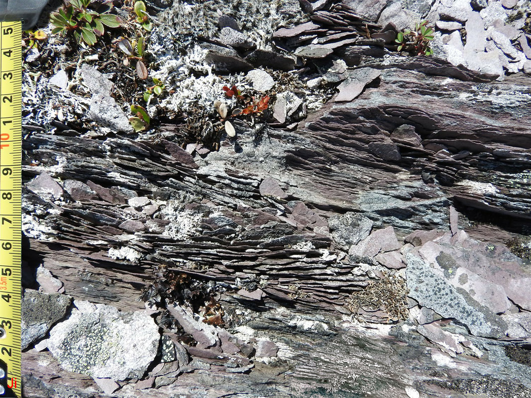
Evidence of small-scale delamination of bedrock and vertical ice-driven shifting of resultant shards can be seen in the above photo. When viewing a scene such as is shown above, it must be remembered that the host rock is well indurated, that is, the rock is not at all friable and is difficult to delaminate or fracture with a hammer. The intrusion of subglacial ice into certain portions of the rock has radically altered the apparent characteristics of the affected rock. It is reasonable to draw an analogy between the scene shown above and a large area of meter-scale joint blocks torn from bedrock by intense and widespread frost heave. Although each individual block might be tough and structurally sound, the ice-disrupted aggregate of blocks would appear from a distance to be comprised of rock that was easily broken. As discussed in Illustrative Feature 09, subglacial bedrock frost heave processes appear to operate somewhat independently of scale over four or more orders of magnitude in linear dimensions.
Delamination of bedrock on a sub-millimeter scale, presumably by subglacial ice extrusion, is illustrated in the preceding photo.
The above photo shows bedrock disrupted by ice acting on scales ranging from meter to centimeter or millimeter. Although the larger-scale disruption visible above consists mainly of fissures, meter-scale frost-heaved monoliths were abundant close to the location photographed above.
Supporting the BESIE model - Part 2
Several more examples will now be presented where asymmetry in the nature and severity of erosion occurring on different surfaces of blocks will be interpreted to indicate that erosion patterns seen on the blocks were formed by ice extruded in a subglacial environment. The purpose of these additional examples is to build further confidence in the validity of the BESIE interpretation by increasing the size of the sample used to support the interpretation. Since the examples consist mainly of frost-heaved joint blocks that have experienced asymmetric grooved erosion, a discussion of the surfaces of frost-heaved joint blocks will precede the examples.
Failure modes and surfaces of joint blocks
A rectangular joint block released from foliated bedrock will typically possess two surfaces parallel to the plane of foliation (foliation surfaces), three surfaces at steep angles (often 60 degrees or 90 degrees) to the plane of foliation (cross joint surfaces), and a top surface defined by prior basal-sliding glacial erosion. The top surface is usually at a steep angle to the plane of foliation. The surface opposite to the top surface (the bottom surface) may be defined by a cross joint or it may be an irregular surface resulting from the tearing of rock by ice pressure acting in the absence of a cross joint. The two surfaces that are not top, bottom or foliation surfaces are usually defined by cross joints, but can sometimes be the result of the tearing of bedrock or the failure of bedrock along smooth but curved weaknesses.
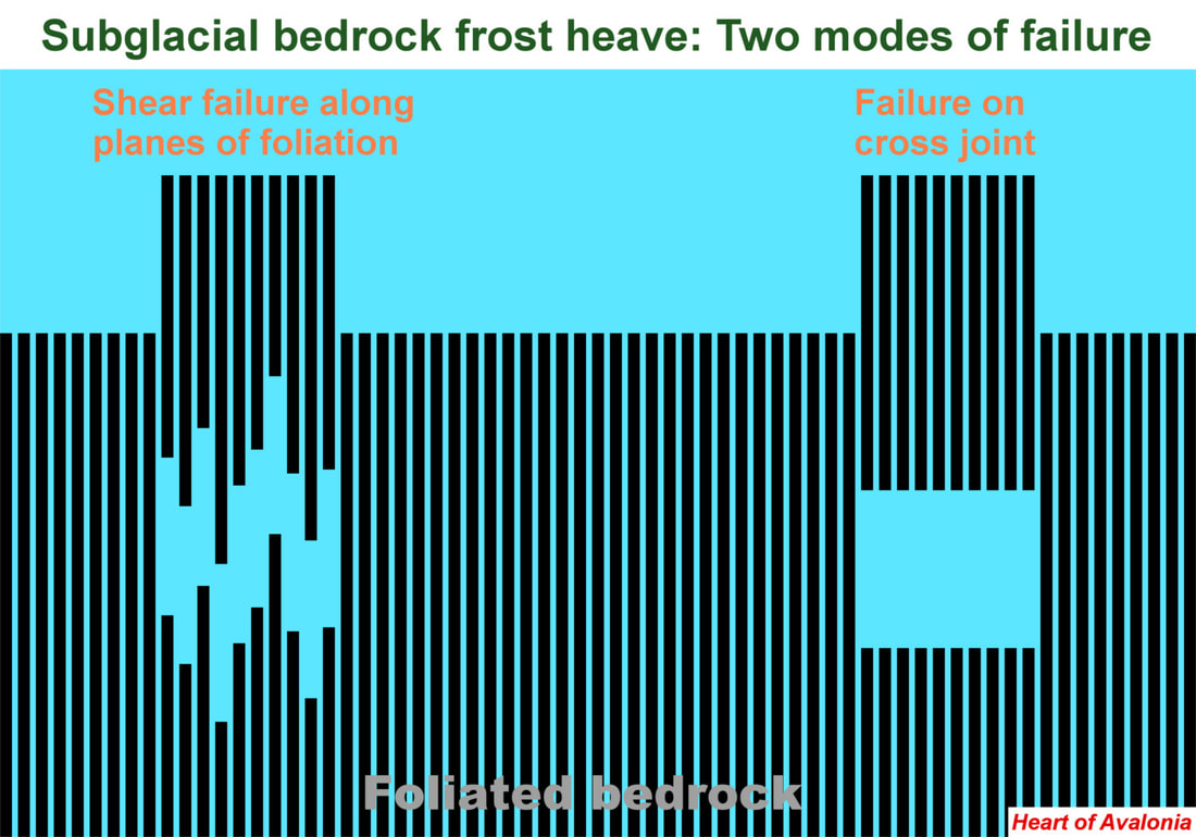
When foliated bedrock is torn apart, failure can occur by shearing along multiple parallel planes of foliation. This failure mode can create a grooved surface potentially mimicking a surface formed by subglacial ice extrusion. In such cases it might be ambiguous to determine the top surface of a block from a torn bottom surface or a torn side surface. The diagram below illustrates the tearing mode of failure and compares this mode with failure along a cross joint at the bottom of a frost-heaved block.
When foliated bedrock is torn apart, failure can occur by shearing along multiple parallel planes of foliation. This failure mode can create a grooved surface potentially mimicking a surface formed by subglacial ice extrusion. In such cases it might be ambiguous to determine the top surface of a block from a torn bottom surface or a torn side surface. The diagram below illustrates the tearing mode of failure and compares this mode with failure along a cross joint at the bottom of a frost-heaved block.
Both modes of failure illustrated in the above diagram can be found in frost-heaved joint blocks observed in the field. Visual access to the bottom of frost-heaved blocks is usually not available unless the blocks have been completely ejected from bedrock substrate. When ejected blocks have been glacially transported, ambiguities can arise in identifying the original tops, bottoms and sides of the blocks. The examples below feature cases where visual access was available and ambiguity did not impede the identification of surfaces.
The block seen near the center of the above frame (block is about 50 cm high) was shifted clear of bedrock substrate by ice extruded from below. Note the characteristic ice extrusion grooves visible on the adjacent block just to the right. The ejected block was detached from bedrock by tear failure on its bottom surface. A closeup showing detail on the torn bottom surface is provided below.
A camera was inserted into the slot beneath the block shown above to record an image of the bottom of the block. The image of the bottom of the block is shown below.
The above photo illustrates the potential difficulty in unambiguously differentiating between the top and bottom surfaces of a glacially-transported frost-heaved joint block when the bottom of the block has separated from bedrock by tearing. The surface morphology shown above mimics a grooved surface potentially produced by subglacial ice extrusion. However, a pattern of visible joints widening to grooves is not prominent on the side of the block extending downward toward the bottom of the block (see preceding bottom-profile photo). This could help in differentiating top from bottom. Many frost-heaved joint blocks detach from bedrock along low-dip-angle cross joints, leaving a flat and less ambiguous bottom surface. These cases are easier to interpret than cases where the bottom surface is a torn surface.
The ejected frost-heaved joint block seen in the above photo (block is about 60 cm high) was torn from bedrock substrate, leaving a grooved bottom profile, as shown. The block, and the two neighboring frost-heaved blocks, all demonstrate top-facing grooves characteristic of erosion by ice extrusion. In the case illustrated above, the ice-extrusion grooves on the top surfaces are recognizably distinct from the bottom tear-failure grooves. It should be noted that asymmetry of erosion by rain and frost during the Holocene could, in principle, account for some or all of the distinction evident in the photo. This concern is reduced or eliminated in cases where blocks have rotated 90 degrees about a horizontal axis and have been glacially transported.
The above photo shows a low cliff where indications of erosion by ice extrusion and of tear failure are both demonstrated. Although the distinction between the two resultant surface morphologies is plain, this example suffers from the same ambiguity described in the previous example. That is, Holocene erosion could, in principle, have caused the distinction.
A question regarding the above-pictured outcrop arises when considering why upward-directed frost heave or ice extrusion occurred when the side of the outcrop was not confined by rock. The side surface facing the camera is a cross-joint failure surface where rock was sheared off and transported to distance by prior basal-slip glacial action. When the glacial ice cover transitioned from warm-based to cold-based, the side facing the camera was confined by cold glacial ice. Evidence from nearby rotated bedrock frost-heave features suggests that deformational flow of the cold ice was directed against the cliff face shown. Accordingly, glaciodynamic ice pressure plus hydrostatic ice pressure against the side of the cliff could exceed the hydrostatic ice pressure at the top of the cliff. Extruded ice originating from the freezing of subglacial groundwater would then be directed preferentially upward.
A question regarding the above-pictured outcrop arises when considering why upward-directed frost heave or ice extrusion occurred when the side of the outcrop was not confined by rock. The side surface facing the camera is a cross-joint failure surface where rock was sheared off and transported to distance by prior basal-slip glacial action. When the glacial ice cover transitioned from warm-based to cold-based, the side facing the camera was confined by cold glacial ice. Evidence from nearby rotated bedrock frost-heave features suggests that deformational flow of the cold ice was directed against the cliff face shown. Accordingly, glaciodynamic ice pressure plus hydrostatic ice pressure against the side of the cliff could exceed the hydrostatic ice pressure at the top of the cliff. Extruded ice originating from the freezing of subglacial groundwater would then be directed preferentially upward.
The above photo shows glacially-deflected frost-heaved joint blocks. The rectangular bottoms of the blocks imply failure on a cross joint with a low angle of dip. The tops of the blocks show indications of erosion by subglacial ice extrusion, although the lack of symmetrical equivalence between the top and bottom surfaces leaves open the possibility that Holocene erosion affected these surfaces differently. If the above-pictured blocks were to have been completely ejected from substrate before the Holocene, and rotated to lie with the plane of foliation at a low angle of dip, then the blocks would more conclusively demonstrate BESIE.
Views of a large frost-heaved monolith with an accessible bottom surface are shown above. This rectangular monolith is defined by three cross-joint surfaces, two foliation surfaces and one basal-slip glacial erosion surface (the top surface). The block lacks indication of erosion by subglacial ice extrusion. The tilt of the block could have resulted from uneven rates of ice accumulation across the bottom surface, but it appears more likely that the tilt was caused by deformational flow of overlying cold glacial ice.
More BESIE examples
The 12 additional examples presented below were chosen to demonstrate evidence of bedrock erosion by subglacial ice extrusion in a range of sample sizes and geometries.
Example 1
Example 1
The foreground of the above photo shows a bedrock outcrop that has been affected by subglacial ice extrusion. The large block in the background is a glacially transported frost-heaved joint block. Peat and vegetation cover the ground sufficiently to conceal the point of origin of the glacially-shifted block. However, since the composition and texture of the block closely matches nearby bedrock it is reasonable to assume that the block has not traveled more than a few meters or tens of meters. Views of the presumed top and bottom of the block are shown below.
The picture on the left above shows the presumed original top of the frost-heaved joint block facing the camera (top before ejection from bedrock), while the picture on the right (camera aim redirected by 180 degrees) shows the original bottom. This block demonstrates a strongly asymmetric erosion pattern, indicating that erosion took place before frost heave and transport. Therefore the erosion took place in a subglacial environment. This example provides convincing support for the BESIE model.
Example 2
Example 2
The boulder shown above is composed of homogeneous fine-grained and well-indurated sedimentary rock. The striking erosion pattern, featuring deep grooves paralleling foliation, suggests erosion by subglacial ice extrusion. The block has been glacially transported, but occurs in an area affected by intense and abundant occurrences of bedrock frost heave. The opposing side of the block is shown in the photo below.
The distinct difference in the nature and extent of erosion on the above-pictured side of the block, considered in comparison with the deeply grooved erosion pattern on the opposing side, would be unexpected in an approximately symmetrical Holocene erosion environment. The block shown above is a good candidate for interpretation as a glacially transported frost-heaved block that was eroded by subglacial ice extrusion. The original bottom of the block is shown above.
Example 3
Example 3
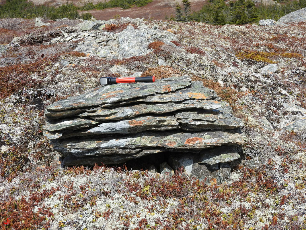
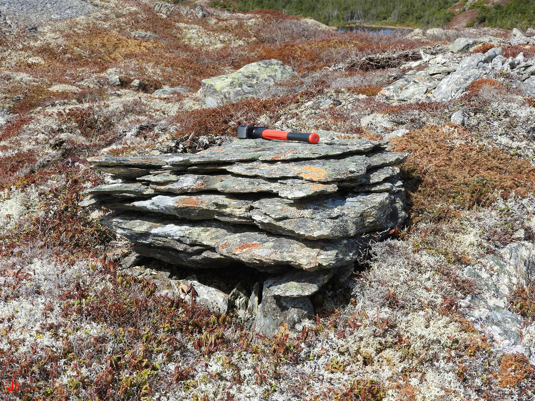
The above photo shows two groupings of ice-disrupted bedrock that can be interpreted as indicating two subglacial ice plume occurrences. A block appearing in the foreground and lying at a low angle to the horizontal is presumably an ejected frost-heaved joint block.
The two views shown above suggest that the prominently visible loose joint block has rotated from its initial orientation, but has not been translated by glacial action. Accordingly, it is easy to unambiguously identify the original top and bottom surfaces of the block. The original top surface faces approximately leftward in both of the above photos.
Views of the original bottom surface of the ejected block are shown above.
Views of the original top surface of the ejected block are shown above.
A view of a side surface of the ejected block is shown above. The block illustrated in the preceding eight photos provides an excellent candidate for interpretation as an example of erosion by subglacial ice extrusion.
Example 4
Example 4
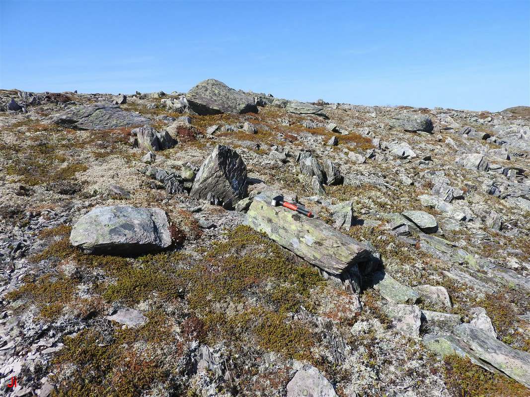
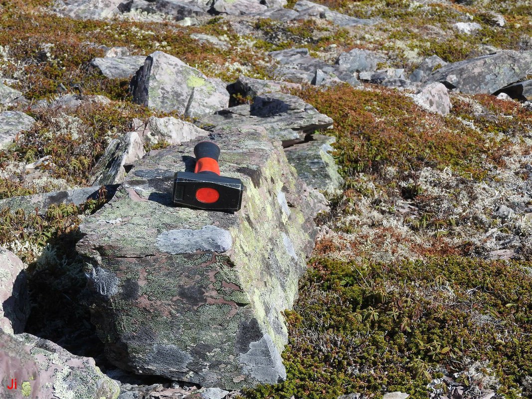
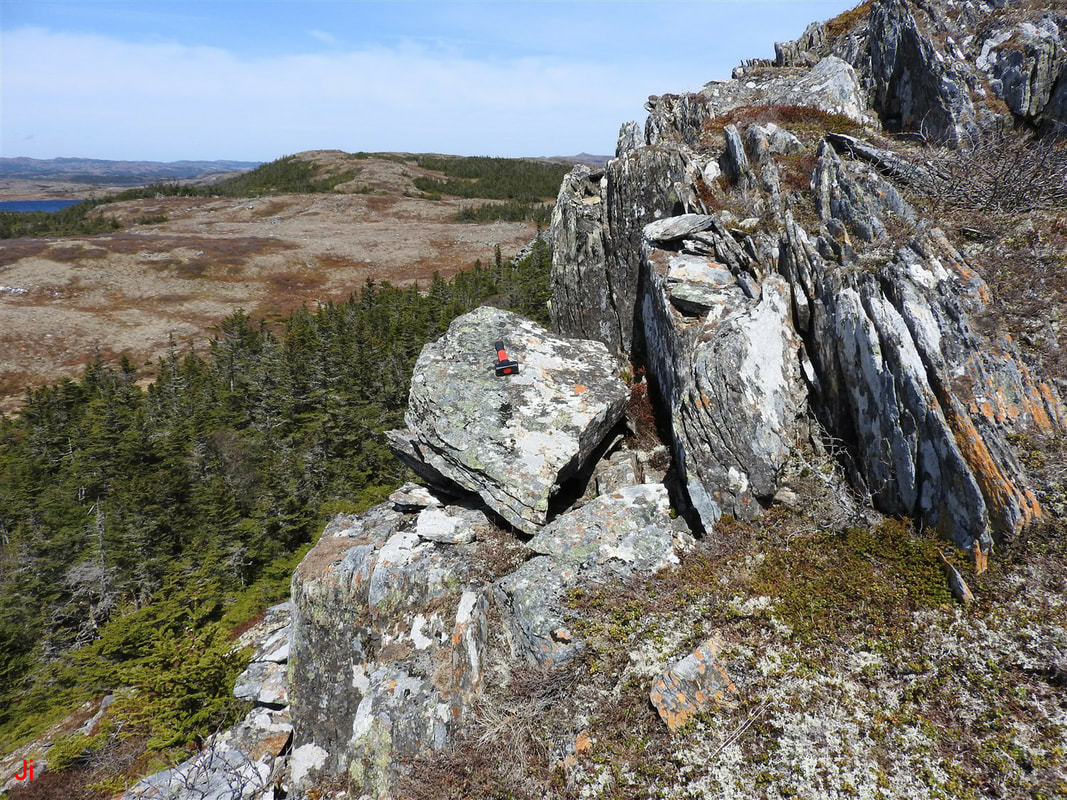
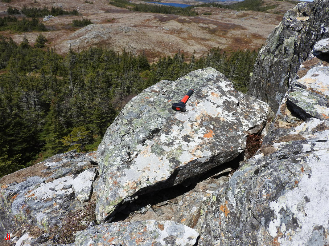
The block seen beneath the hammer in the above photo is an ejected (from nearby bedrock) frost-heaved joint block that has rotated about a horizontal axis and has been glacially transported. Almost all of the rocks appearing in the background are of subglacial frost heave origin, with some of the blocks remaining rooted in bedrock while others have been glacially transported.
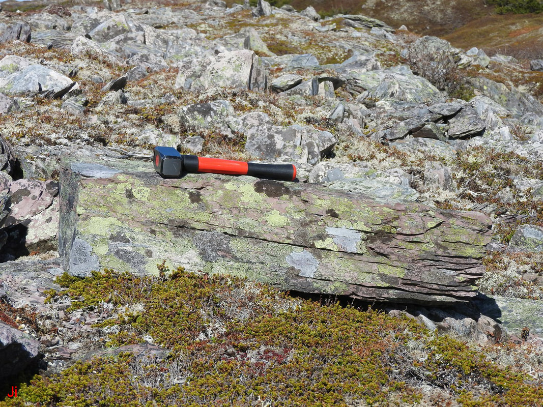
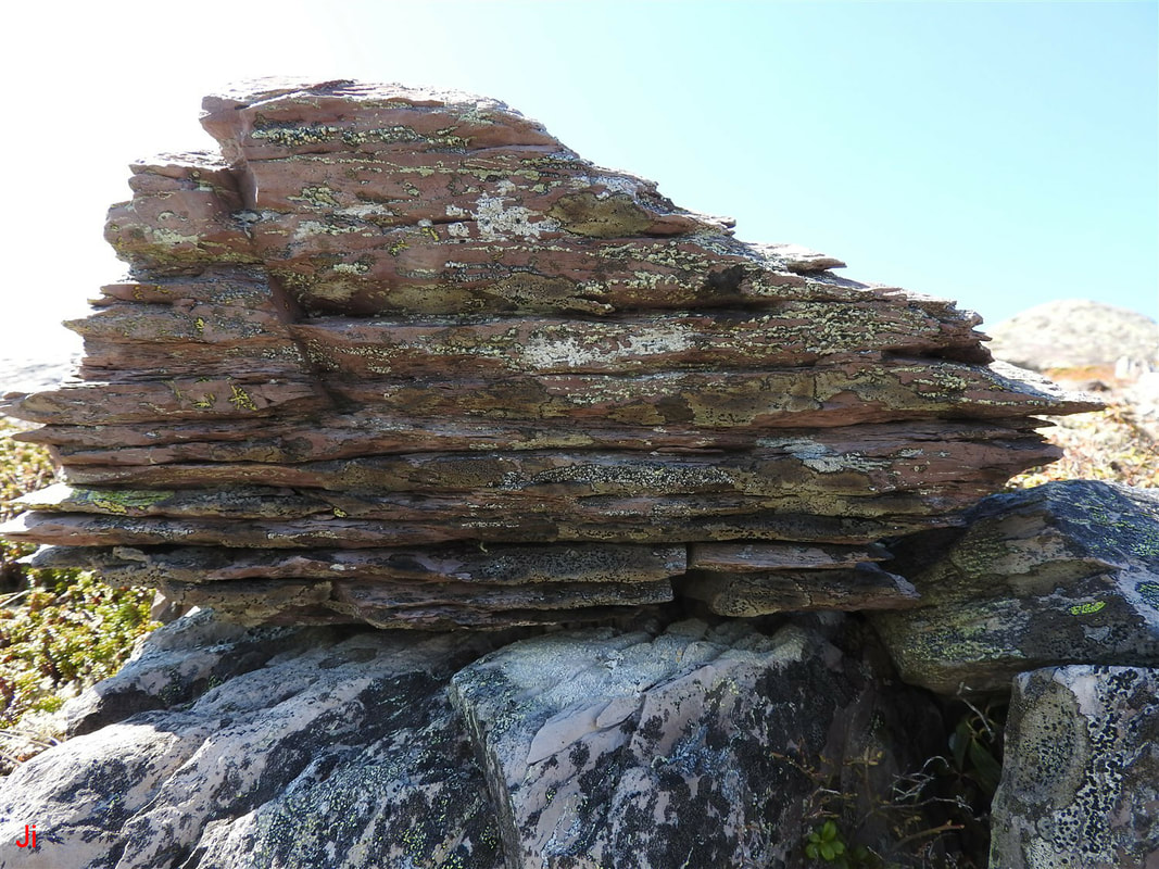
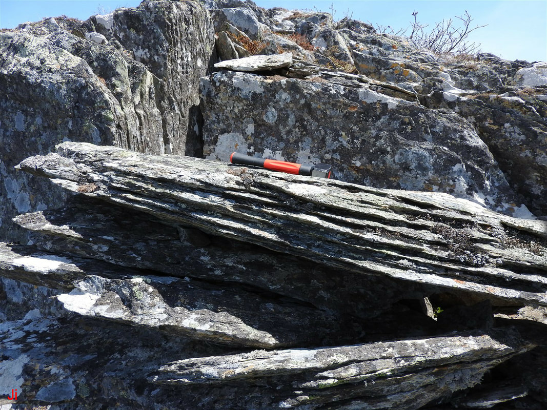
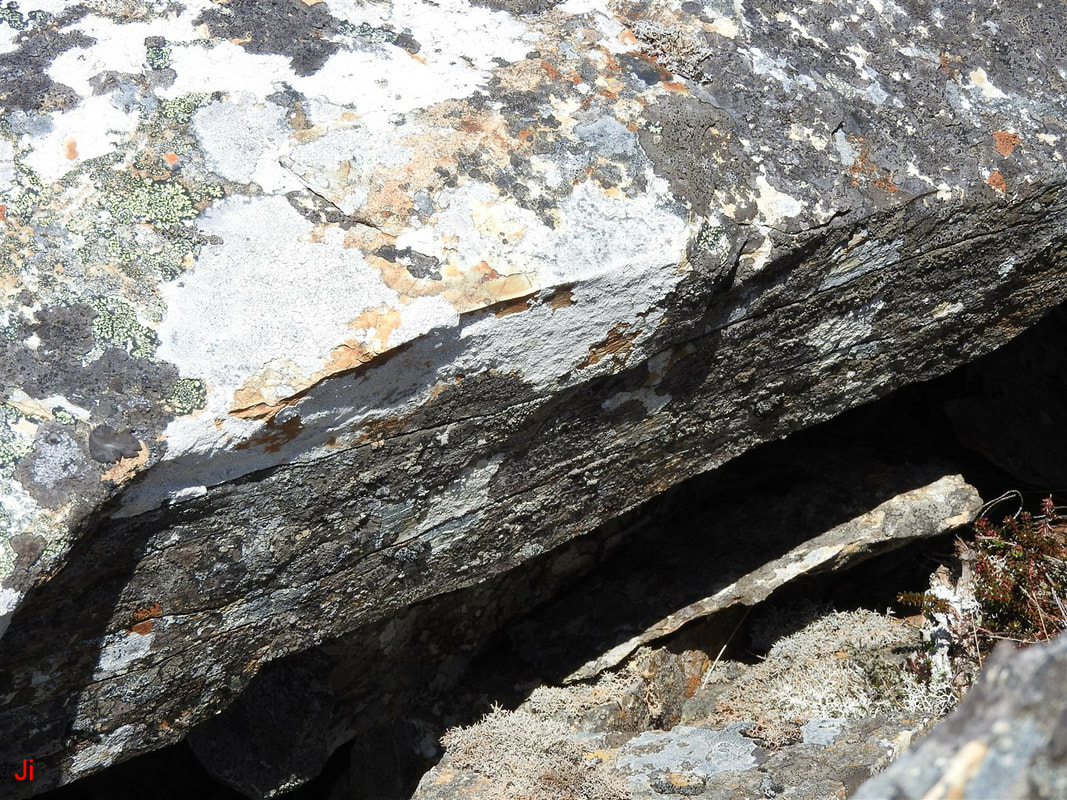
A closeup of the dislodged frost-heaved joint block is shown above. The characteristic pattern of grooves tapering inward to joints, indicating erosion by subglacial ice extrusion, can be seen on the side of the block facing the camera. The presumed original bottom of the block lies at the left in the above photo, while the presumed original top lies at the right. Closeups of these surfaces are shown below.
The original bottom of the block is shown in the first (left) photo above, while the original top of the block is shown in the second (right) photo above. The strong contrast between the erosion patterns seen on the opposing surfaces clearly implies that the erosion took place before the block assumed its present position and orientation. Given that the eroded grooves visible on the original top surface of the block were formed while the block was buried beneath glacial ice, it is difficult to envision any process other than ice extrusion (that is, small-scale subglacial frost heave) that could account for the formation of the grooves. A hypothesis that perhaps the grooves were formed by surface erosion processes before the Wisconsin glaciation (that is, during the Eemian) is improbable because basal-sliding glacial erosion would likely have erased such fragile features long before the Younger Dryas.
Example 5
Example 5
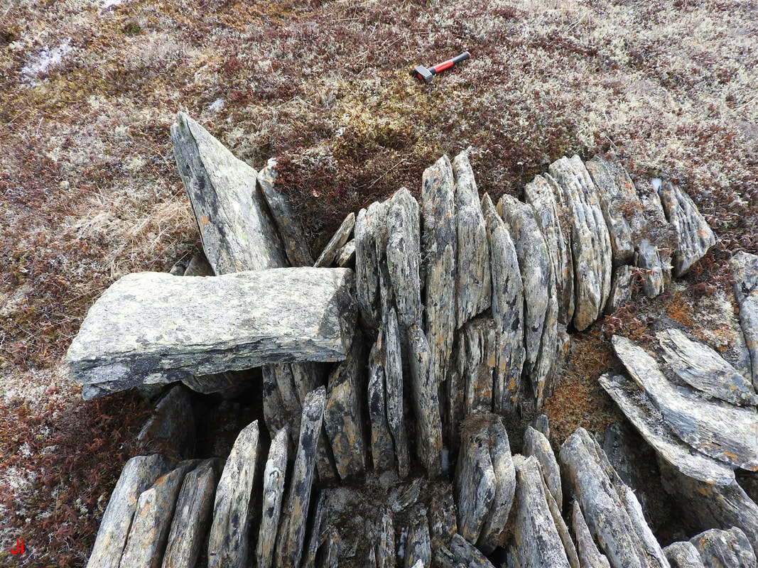
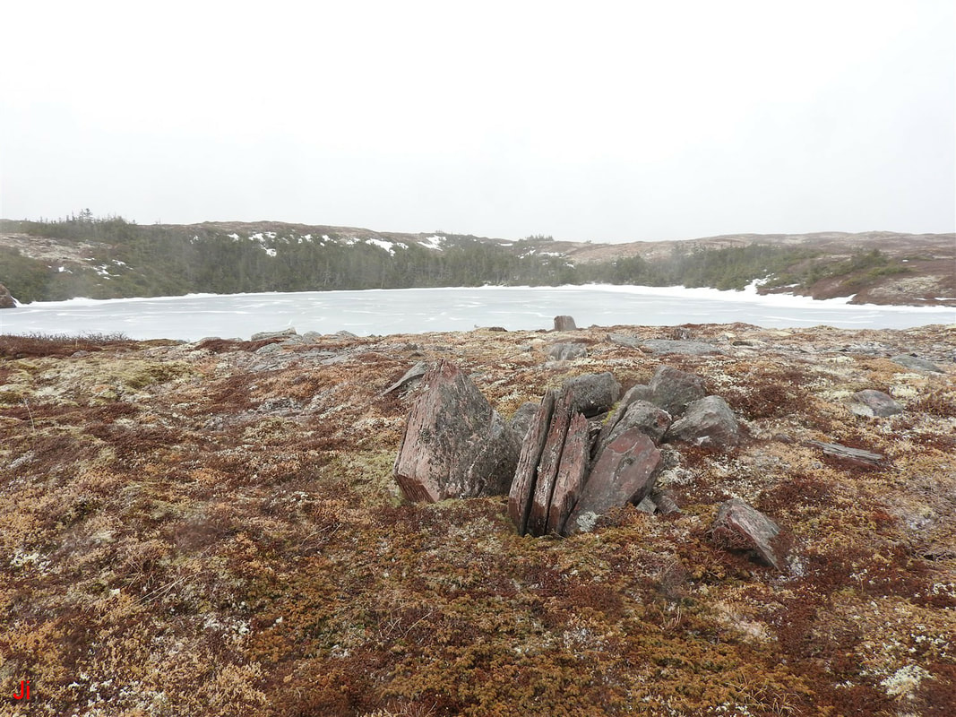
The above photo shows a single frost-heaved bedrock monolith lying to the left of a group of three sections of another frost-heaved bedrock monolith. The illustrated frost-heave occurrence is somewhat unusual because the blocks appear to have been dislodged from substrate, shifted about 30 cm toward the camera, and then tipped back into the underlying cavity after ice departed. As a result, the original bottoms of the blocks are partially exposed. The elongated surfaces seen facing the camera are original side surfaces. The original top surfaces face upward and toward the lake.
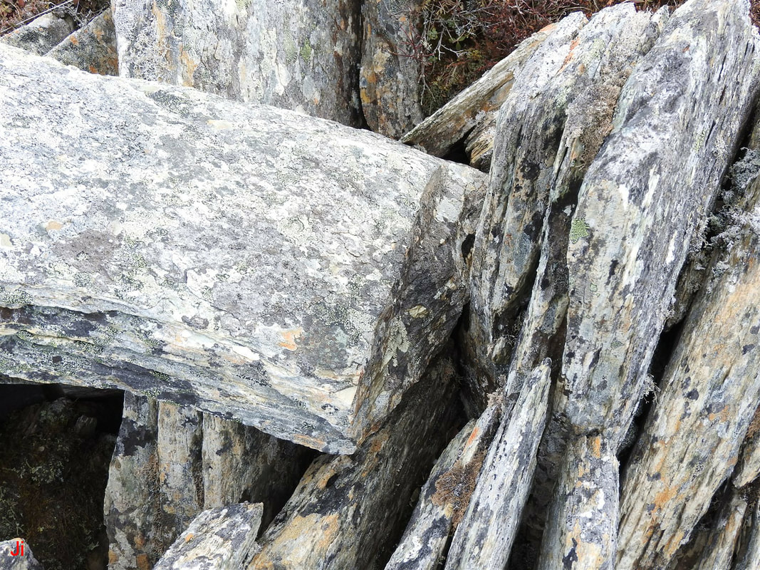
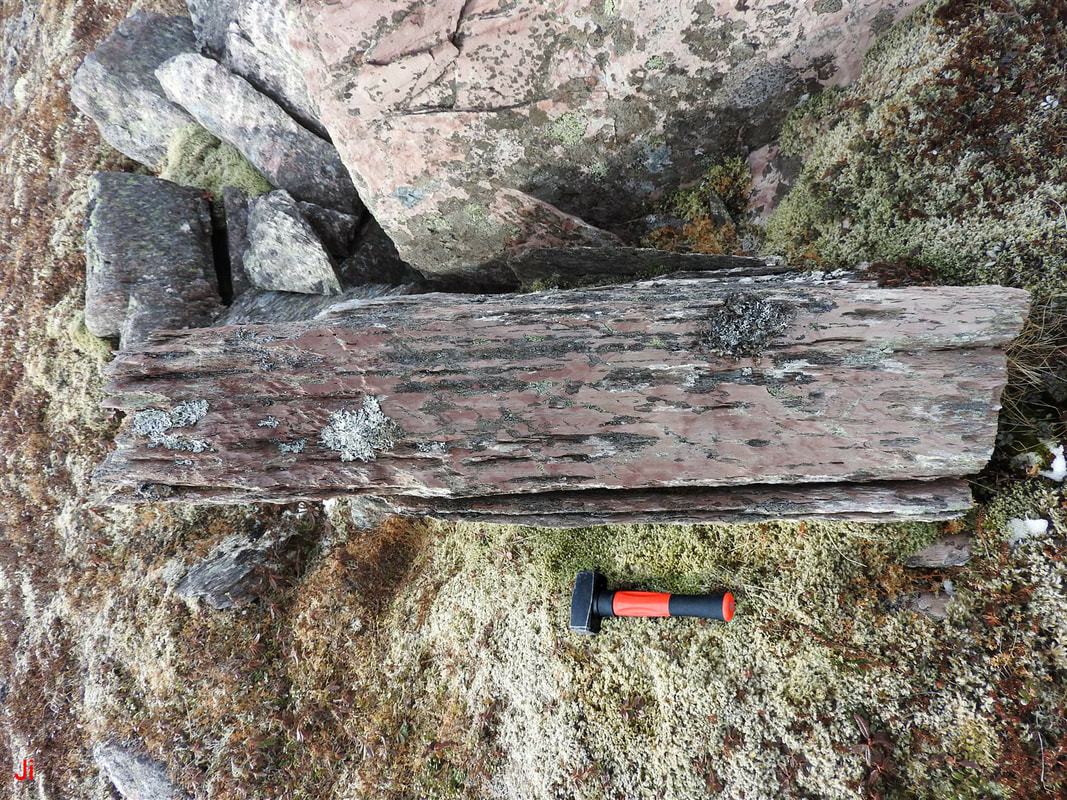
The original side surfaces of the blocks (single block, first photo ; group of three blocks, second photo) are shown above. These surfaces slope upward from the ground at 45 degrees (see previous photo) and the camera was tilted appropriately to properly frame the surfaces. Original tops face left and original bottoms face right. The surfaces show grooves and joints characteristic of erosion by ice extrusion.
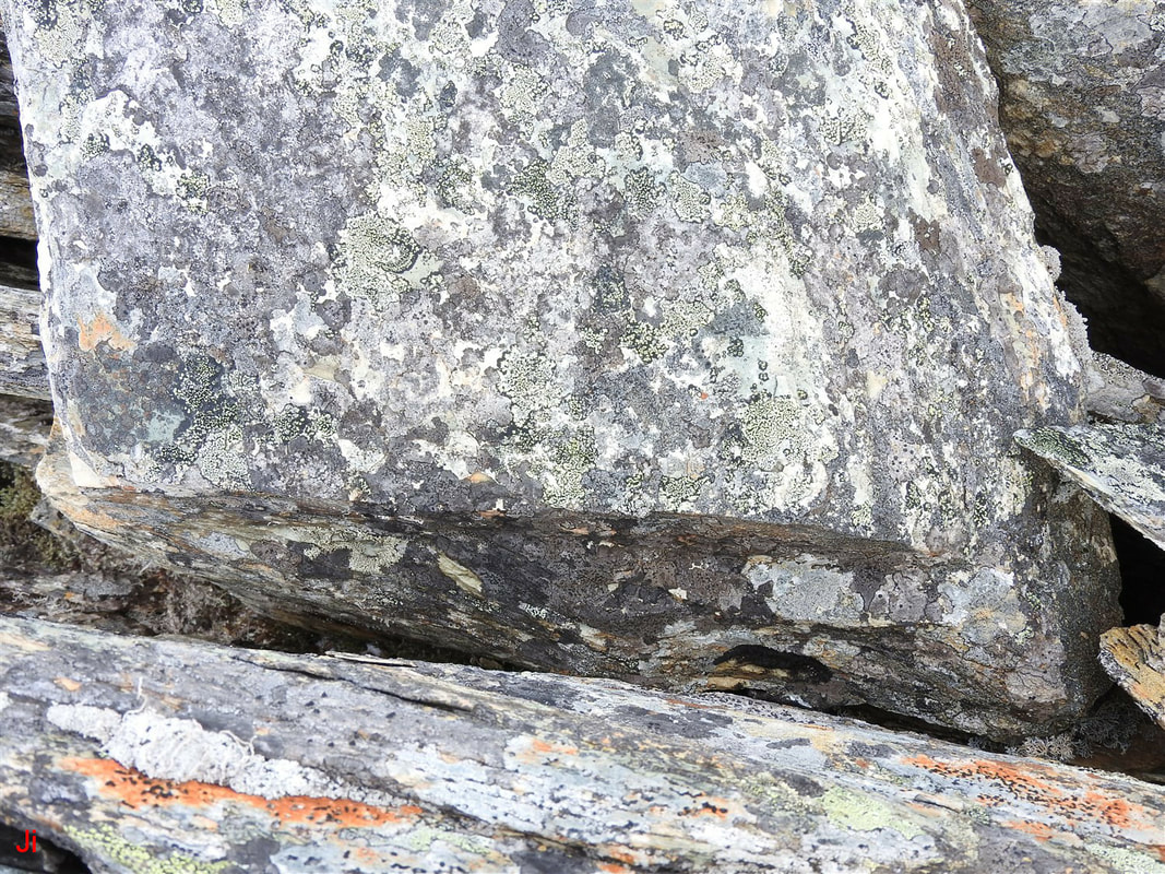
The original tops of the blocks face upward and toward the right in the above photo. These original-top surfaces show a grooved morphology suggesting erosion by ice extrusion. Because of the 45 degree tilting of the joint blocks, there is a rough symmetrical equivalence between present-day surfaces that were originally non-equivalent. The differences in erosion patterns on the original top surfaces versus the original side surfaces can thus reasonably be attributed to erosion that took place before the blocks assumed their present orientations.
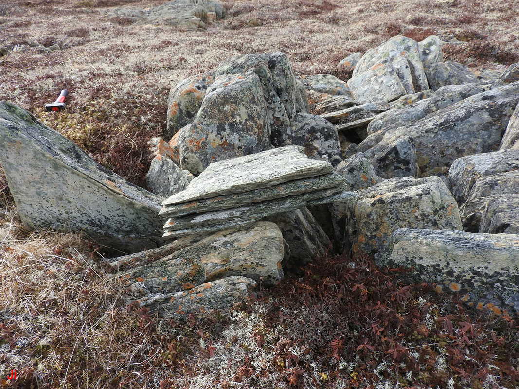
The original bottom surface of the larger (single) joint block is shown above. Note the apparent delamination of the block. The visible joints are presumably collector channels concentrating the movement of water or ice toward the original top of the block.
Example 6
Example 6
The above photo shows a frost-heaved joint block that has evidently been ejected from nearby bedrock substrate, rotated 90 degrees about a horizontal axis, and glacially transported over a short distance. The original top of the block faces the camera, implying that the block has also rotated 90 degrees about a vertical axis. A question arises as to how a joint block, presumably frost-heaved under cold subglacial conditions, can be transported and rotated by a glacier that is frozen to the ground. An explanation exists in recognizing that non-tangential ice flow (that is, the diverging-from-ground flow of extruded ice formed by freezing groundwater) can carry the block aloft into the overlying cold glacier. Deformational flow in the overlying cold glacier can then transport the block a short distance, even if the block remains quite close to the ground. The rotation of the block can occur during settling as ice surrounding the block dissipates during deglaciation. Closeup views of the original top and bottom surfaces of the block are shown below.
The rippled bottom surface of the block (second, right, photo above) suggests that the block separated from substrate by tearing rather than by parting along a low-dip-angle cross joint. Nevertheless, the differences seen in the shape and depth of the grooves affecting the top and bottom sides indicate that the top surface of the block was likely eroded by subglacial ice extrusion.
Example 7
Example 7
Two opposing views of a glacially transported frost-heaved block are shown above. The presumed original-top surface of the block is pictured in the first (left) photo above. Closeups are shown below.
As with previous examples in this section, contrasting erosion patterns on opposing surfaces suggest that the glacially transported joint block underwent erosion by ice extrusion prior to or during frost heave while the block was still registered in bedrock substrate.
Example 8
Example 8
The above three photos show a small glacially transported fragment of an apparent frost-heaved joint block. The lack of eroded grooves on the side surfaces visible in the third (bottom, right) picture supports the hypothesis that the deep, V-shaped grooves characterizing erosion by ice extrusion predate the Holocene.
Example 9
Example 9
Two views of pronounced erosion grooves presumably formed by subglacial ice extrusion are shown in the above photos. The block appears to be divided into loose pieces by the erosion/delamination, but an attempt to pry apart layers indicated that the block was intact and mechanically sound. A view of the opposing side (presumed original bottom) of the glacially transported frost-heaved block is shown below.
Examples such as the one shown above suggest that significant deformational ice flow occurred within bedrock, causing macroscopic internal erosion (erosion by ice extrusion) at depths of centimeters or tens of centimeters below the original glacier-facing surface of the rock.
Example 10
Example 10
The above two photos show a block, indicated by the hammer, lying at the edge of a down-slope where a combination of frost heave and stress from deformational ice flow (glaciotectonic stress) has disrupted the bedrock. The second (right) photo above suggests that ice was being extruded from the ground and was merging with down-slope deformational glacial flow. The block marked by the hammer possesses a prominent asymmetrically occurring grooved pattern indicating erosion by ice extrusion.
The above two photos show the relatively smooth presumed original bottom surface of the frost heaved and glacially shifted block.
The first (left) photo above shows the presumed original top surface of the frost heaved and glacially shifted block. The second (right) photo provides an indication of the depth of the ice-eroded grooves.
Example 11
Example 11
The above photo shows an unusual occurrence where bedrock demonstrating erosion by ice extrusion has also been affected by glaciotectonic action and, potentially by a final stage of abrasive erosion powered by ice moving in basal sliding mode.
The above two photos, taken from opposite sides of the small outcrop, clearly suggest that the rock has been streamlined and curved by overhead abrasive action. It is possible, although seemingly improbable, that blocks were dragged over the outcrop by a cold glacier. The abrading blocks would need to have extended far enough up into the overlying ice to experience substantial loading by ice moving via deformation. The outcrop sits near the top of a long, steep slope, a location where significant near-ground ice creep would be favored. Alternatively, the erosion could have been caused by conventional basal-sliding action during the late stages of deglaciation. This forces the assumption that originally cold-based glacial ice transitioned back to warm-based glacial ice at this particular location. Examples of frost-heaved bedrock that has been eroded by glacial abrasion have been found at other locations on the Avalon Peninsula, but they are rare. There is little evidence of this phenomenon having occurred widely in the major frost-heave affected areas of the Avalon Peninsula, but local late-stage reversion back to warm-based glacial ice flow cannot be entirely ruled out everywhere.
A photo of the outcrop taken from an angle chosen to highlight grooves formed by ice extrusion is shown above. Clearly, the foliation in the bedrock has been deflected from its normal, near-vertical angle of dip, by glaciotectonic stress. However, the rock has not failed by shearing between successive layers. All of the rock layers seen in the central portion of the above photo are mechanically bonded. A single block has apparently been separated from bedrock, and then been rotated and smoothed by a combination of ice extrusion and loading and abrasion from moving glacial ice. The apparent delamination of the rock is caused exclusively by ice extrusion.
Example 12
Example 12
The above two photos show a bedrock outcrop forming a low cliff part way down a steep slope. The section of bedrock beneath the hammer, and the lower section to the immediate left, both show the typical groove and joint patterns characterizing erosion by ice extrusion. Considered in isolation, the observed groove patterns could be interpreted as a result of rainwater erosion and/or a result of frost wedging occurring during Holocene winters. However, a large foreground block of the same bedrock has tipped over and is now lying at roughly 80 degrees (rotation about a horizontal axis) to its original orientation. This block, shown below, possesses grooved erosion patterns similar to those shown above.
It appears possible, in principle, that the detached block seen in the above photo broke away from bedrock and toppled to its present position post-deglaciation. However, this interpretation seems less probable than the possibility that the block was shifted to its present position by glacial action. The present position and orientation of the block (marked by the hammer) imply an unlikely bounce when the block fell. Furthermore, any nearby horizontal surface from which the block might have detached is now cluttered with other blocks. A question arises regarding how the fragments now occupying the detachment surface could assume their positions post-detachment without having been transported by glacial ice.
If it is assumed that glacial action was responsible for separating the large block from bedrock and placing it at its present location, then the similarity of the eroded grooves seen in the displaced block to those seen in the above-pictured intact bedrock becomes an unlikely coincidence, given the assumption of a Holocene origin for the erosion. Rather, it becomes more probable that the grooves were eroded on both the fallen block and the nearby intact bedrock at a similar time, before glacial ice departed. The photos below show details of the erosion on the original top and the original bottom surfaces of the fallen block.
If it is assumed that glacial action was responsible for separating the large block from bedrock and placing it at its present location, then the similarity of the eroded grooves seen in the displaced block to those seen in the above-pictured intact bedrock becomes an unlikely coincidence, given the assumption of a Holocene origin for the erosion. Rather, it becomes more probable that the grooves were eroded on both the fallen block and the nearby intact bedrock at a similar time, before glacial ice departed. The photos below show details of the erosion on the original top and the original bottom surfaces of the fallen block.
The original bottom of the fallen block can be seen in the above photo. Contrasting closeups of the original top of the block and the original bottom of the block are shown below.
Unlike the previous examples in this section, the block illustrated above is not a frost-heaved joint block. Rather the block has been separated from bedrock and displaced primarily by the mechanical action of moving glacial ice. Nevertheless, the block shows contrasting original top (first, left photo above) and original bottom (second, right photo above) surfaces that are typical of other blocks presumed to demonstrate erosion by ice extrusion.
Conclusion
The discussion and examples provided above were chosen to increase confidence in the BESIE model for explaining grooved erosion patterns observed in rock that is closely geographically associated with occurrences of subglacial bedrock frost heave. Bedrock erosion by subglacial ice extrusion should be considered a form of bedrock frost heave, whereby small frost-heaved fragments are typically removed from the area of their formation, leaving behind an empty depression in a bedrock surface. It has not yet been fully determined why the impact of BESIE on homogeneous, fine-grained foliated rock is to generate a repeating pattern of long linear grooves. However, an association of the eroded grooves with a pattern of visibly widened joints, connected to the grooves and reaching deep into underlying bedrock has been identified. The linearity of the grooves is a likely consequence of the planar nature of the connected feeder joints. This planar nature reflects foliation in the rock and the large extent of non-random alignment of microscopic, platey, phyllosilicate crystals that can be wedged apart by intruding groundwater (pore water) and associated segregating ice.
Analysis of occurrences of BESIE can potentially lead to an understanding of the propagation of groundwater to the surface of subglacial frozen bedrock. An understanding of the mechanisms for sourcing and propagating subglacial groundwater will help in understanding all aspects of subglacial bedrock frost heave.
Analysis of occurrences of BESIE can potentially lead to an understanding of the propagation of groundwater to the surface of subglacial frozen bedrock. An understanding of the mechanisms for sourcing and propagating subglacial groundwater will help in understanding all aspects of subglacial bedrock frost heave.
heartofavalonia.org Exploring Geologic History
