Frost-heaved Bedrock: Illustrative Feature 04
Alignment of dislodged frost-heaved joint blocks by ice creep.
Subglacial frost heave.
Isthmus of Avalon
Alignment of dislodged frost-heaved joint blocks by ice creep.
Subglacial frost heave.
Isthmus of Avalon
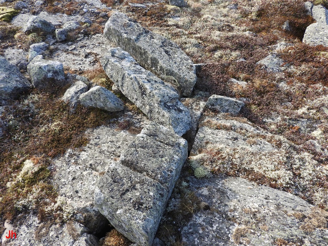
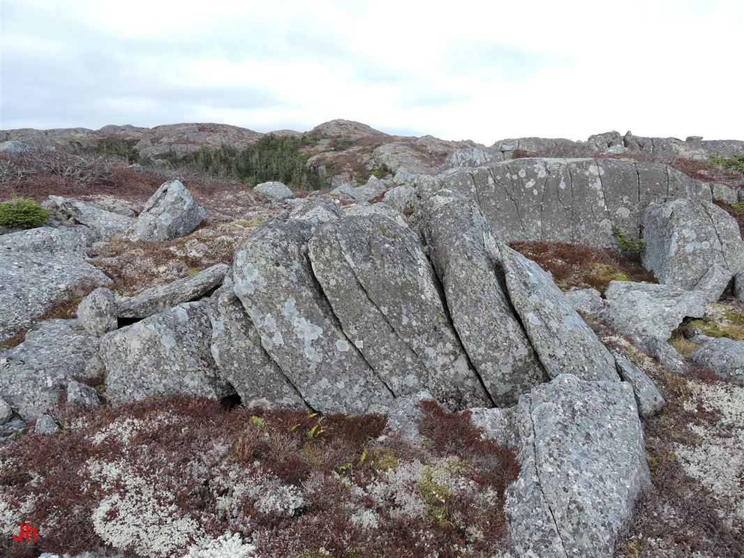
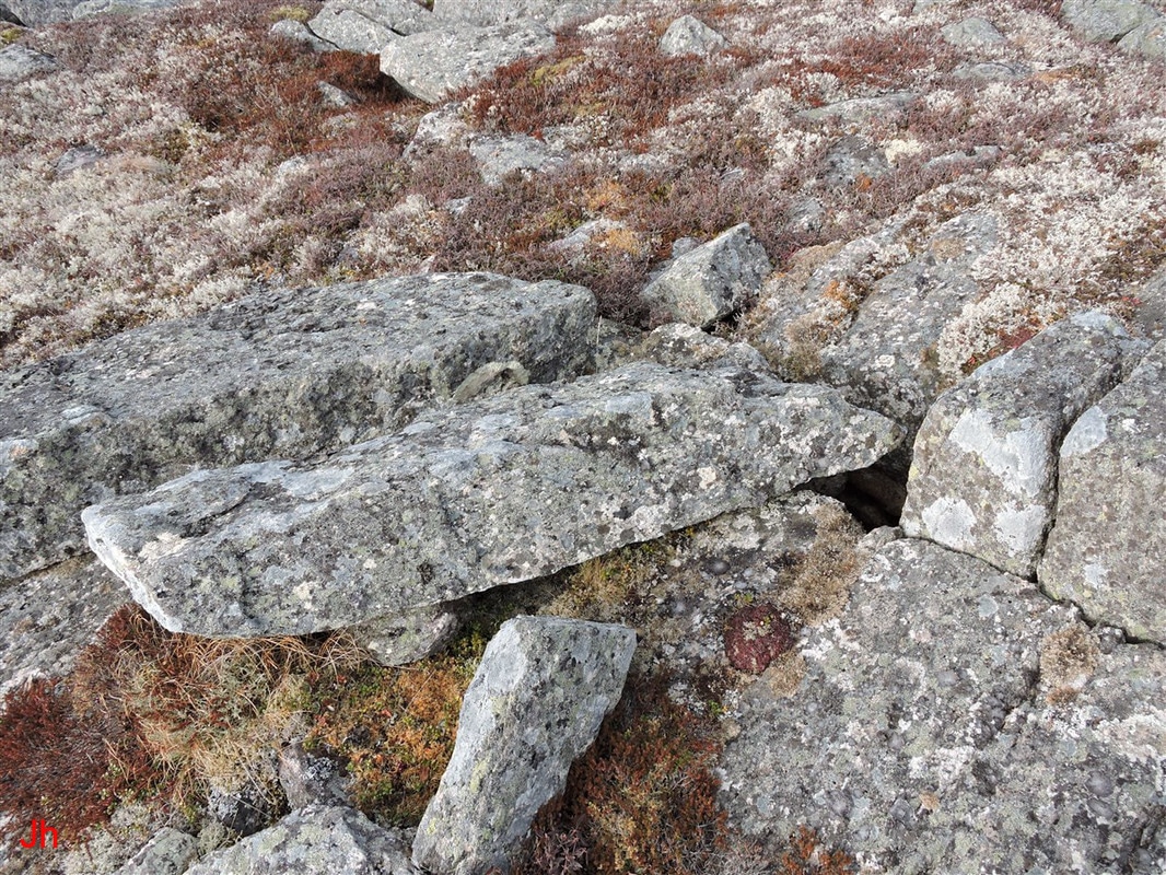
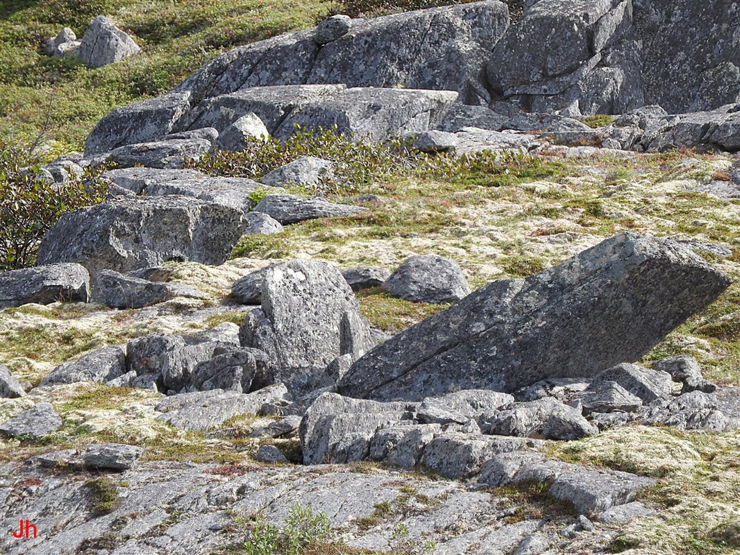
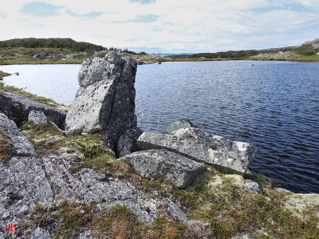
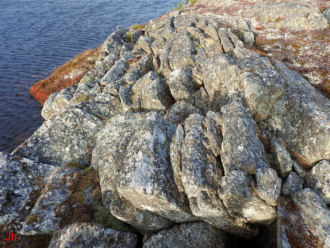
The above photo shows two frost-heaved joint blocks (blocks ~1.5 m long) that have been dislodged from a horizontal bedrock surface. Another frost-heaved block appears in the foreground, but this block (separated into 3 sections) remains rooted. Using evidence from the layout pictured above and other nearby features, it will be argued that the frost heave event shown here occurred in a subglacial environment and that the orientation of the dislodged blocks indicates glacial creep.
Why is this feature (IF04) significant?
Most bedrock frost heave features originate subaerially under periglacial climate conditions and their formation is dependent on seasonally-induced temperature gradients. Since the subaerial, thermally driven frost heave model is well supported by theory and by present-day observations in polar regions, it is reasonable to extend the model to include the relict frost-heave features seen on the Isthmus of Avalon. Within the context of the thermal-origin model, a section of bedrock can be pushed upward during development of an underlying ice mass via ice segregation, and the resultant block can topple, potentially creating a scene similar to that shown above. Subsequent encroachment of a glacier would provide further flexibility of interpretation if the late-intruding glacial ice was suspected of moving the toppled block horizontally. With such considerations taken into account, turning away from the subaerial/thermal-origin model in favor of a subglacial-origin model requires specially-focused observations that help to differentiate between the two possibilities.
The rock shifts observed and presented as IF04 show a consistency of alignment that suggests glacial flow caused or influenced horizontal changes in their positions and orientations. The key question then becomes one of timing. Could the glacial activity have occurred following a subaerial occurrence of thermally-driven bedrock frost heave, or is it more reasonable to assume that the glacial activity was simultaneous with the frost-heave event? In the latter instance, the frost heave would be, by definition, subglacial. Clearly, glacial ice encroaching on a dislodged boulder can move the boulder, but it is less obvious that there would be a tendency to align an elongated block in the direction of ice flow. A completely loose block might simply orient itself randomly when moved by ice across an irregular surface. Alternatively, an elongated block might be expected to align broadside against an ice edge in cases where the loose block was contacted by the edge of an encroaching glacier.
As discussed in Technical Note 07, alignment of a dislodged elongated block in the direction of ice flow becomes more likely when two conditions are met. 1) The frost-heaved block topples from the underlying cavity while embedded in a moving ice stream. 2) The ice-stream motion is via creep, not basal sliding. A third condition might entail limiting total horizontal motion, but this condition stems mainly from the difficulty in reconstructing an event if a large amount of horizontal motion has taken place.
The observations to be presented below as IF04 demonstrate the presence and action of a glacier in a local area and establish an ice flow direction. The observations can further be regarded as indications of glacially guided bedrock frost heave. If the observations warrant this proposed interpretation, then the illustrated frost heave was subglacial in origin, and furthermore the glacial ice thickness present during frost heave was sufficient to overcome topographic barriers, hence more than 100 meters. Such an interpretation would reinforce the interpretations of IF01, IF02 and IF03 and add further weight to the argument that subglacial bedrock frost heave was a significant occurrence on the Isthmus of Avalon.
IF04 consists of five closely spaced individual features, two ice flow indicators and three instances of dislodged and aligned frost-heaved joint blocks. The relative positions of the five features are illustrated on the following map.
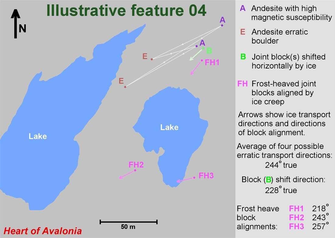
The five features located on the above map will be described individually below. Each feature is identified by the symbol indicated on the map. Arrows show alignment directions or indicated ice flow directions.
Andesite outcrops (A) and erratics (E):
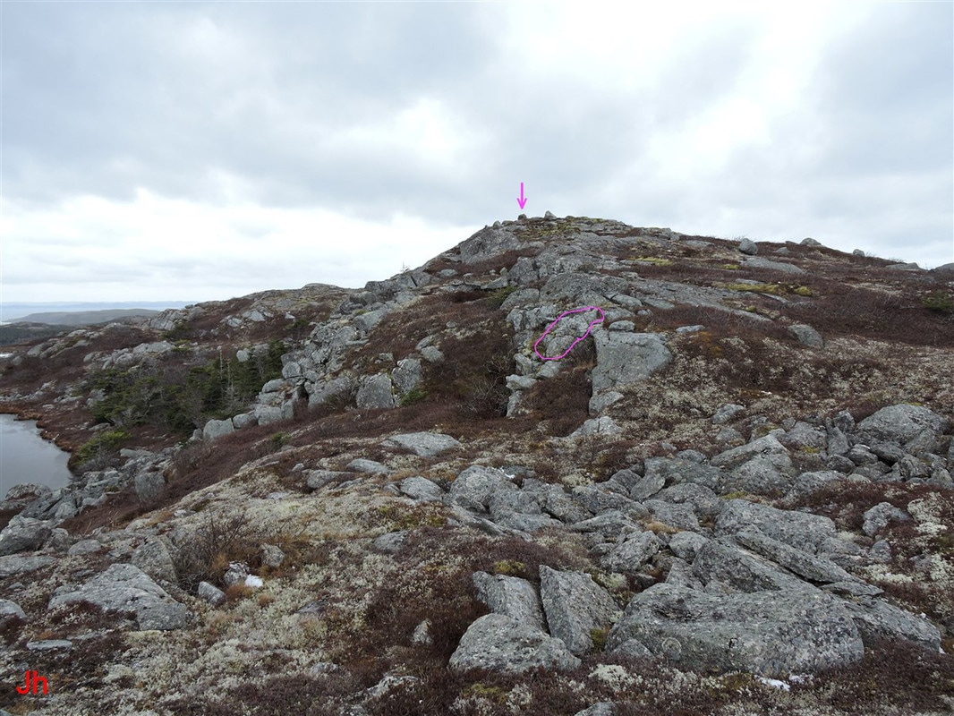
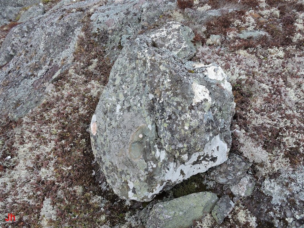
Two small outcrops of andesite having an unusually high magnetic susceptibility were identified in the area under consideration. The outcrops, each measuring only a few metres in dimensions, were detected by their characteristic appearance and lichen coverage and then confirmed using a hand magnet (more discussion of magnetite-rich andesite will be presented in the section "High Susceptibility" of Heart of Avalonia (pending)). The andesite had intruded the metasomatized tuff and ignimbrite comprising the majority of the rocks in the local area. A search turned up only two small andesite outcrops, each apparently exposed by glacial erosion. A corresponding search for andesite-bearing erratics revealed two boulders, each readily recognizable by its unusually high magnetic susceptibility. The positions of the erratic boulders and the potential source outcrops are indicated on the above map (A: andesite outcrop, E: erratic boulder). The first (left) photo below shows one of the andesite outcrops (circled in magenta) and one of the erratics (magenta arrow). The second (right) photo shows a closeup of the same andesite-containing erratic boulder seen in the first (left) photo. The small button magnet seen adhering to the boulder in the second (right) photo (small, hard to see) is 1.7 cm in diameter.
Andesite outcrops (A) and erratics (E):
Two small outcrops of andesite having an unusually high magnetic susceptibility were identified in the area under consideration. The outcrops, each measuring only a few metres in dimensions, were detected by their characteristic appearance and lichen coverage and then confirmed using a hand magnet (more discussion of magnetite-rich andesite will be presented in the section "High Susceptibility" of Heart of Avalonia (pending)). The andesite had intruded the metasomatized tuff and ignimbrite comprising the majority of the rocks in the local area. A search turned up only two small andesite outcrops, each apparently exposed by glacial erosion. A corresponding search for andesite-bearing erratics revealed two boulders, each readily recognizable by its unusually high magnetic susceptibility. The positions of the erratic boulders and the potential source outcrops are indicated on the above map (A: andesite outcrop, E: erratic boulder). The first (left) photo below shows one of the andesite outcrops (circled in magenta) and one of the erratics (magenta arrow). The second (right) photo shows a closeup of the same andesite-containing erratic boulder seen in the first (left) photo. The small button magnet seen adhering to the boulder in the second (right) photo (small, hard to see) is 1.7 cm in diameter.
|
|
Four possible ice paths link the two andesite-bearing erratics with the two andesite outcrops. These are illustrated on the previous map. Since there was no basis to link a specific erratic with a specific outcrop, the directions of the four paths were averaged to give an implied ice flow direction of 244 degrees true. Both erratics lay at higher elevation than the either of the outcrops, minimizing the possibility that glacial meltwater runoff might have transported them. Using the shifted erratics to determine ice flow was advantageous over using striations in that a possible 180 degree ambiguity in ice flow direction was eliminated.
Joint block(s) shifted horizontally by ice (B):
Joint block(s) shifted horizontally by ice (B):
|
|
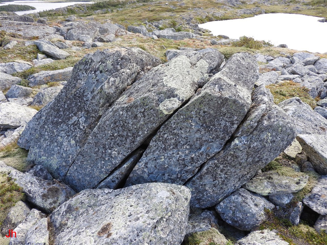
The above two photos show a bedrock outcrop (background in first photo, foreground in second photo) with two exposed failure planes at right angles. The failure plane striking roughly toward the camera follows longitudinal foliation in the bedrock, while the orthogonal failure plane follows cross jointing. Close observation of the tipped assembly of joint blocks seen in the foreground of the first (left) photo and the center of the second (right) photo indicated that this set of blocks was glacially transported (probably starting as a single block) from the corner indentation of the pictured bedrock outcrop. The photo below indicates scale and direction of the ice-induced bedrock shift. A yellow measuring tape (hard to see in photo) extends diagonally from the indent corner in the bedrock outcrop to the mating corner of the shifted block assembly. The tape reads 3.1 meters.
The photos below show closeups of the shifted block(s).
|
|
The first (left) photo above shows the block(s) viewed from the south, looking north while the second (right) photo shows the view from the opposite direction. The block assembly is about 2.8 m end-to end and stands about 1.4 m high as measured orthogonal to the ground. The width of the assembly averages about 2 meters. The dimensions of the assembly of blocks make a good match with the corresponding measurements of the bedrock indent. Examination of the base of the block assembly revealed that the blocks are not connected to the underlying bedrock, although they are sunk down a few centimeters into the peat.
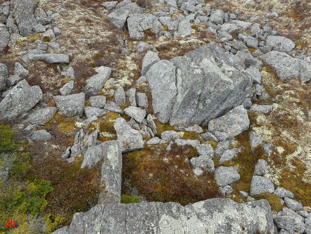
An overhead view of the displaced-block feature is shown above. This view forms the basis for the following diagram which illustrates the apparent ice-induced trajectory of the block assembly.
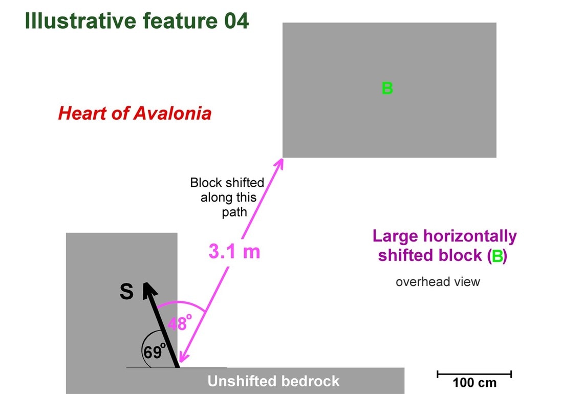
The model for explaining the displacement of the block assembly as illustrated above, incorporates an element of hydraulic bedrock frost heave and then subsequent horizontal shifting of the frost-heaved block assembly via creep of an overlying cold-based glacier. In this model, the process commences with the entry of pressurized groundwater/ice into a horizontal joint at the base of the block assembly. This horizontal joint (failure plane) was at about the same level as the surface of adjacent bedrock (ground surface) lying southwest of the feature (failure along this joint plane during an earlier episode of basal-slip glacial erosion could have defined the adjacent ground surface).
Subglacial frost heave lifted the block assembly enough that creep of the overlying glacial ice was able to move the block assembly slightly in a southwesterly direction as illustrated. The ice creep was more rapid at elevation than near the ground, resulting in stress (ice loading) that attempted to tip the block both top-toward-the-south and top-toward-the west. The block fractured at intervals along longitudinal cleavage to accommodate the westerly component of the stress. The southerly ice-load component might also have tilted the block, with the tilt reversing out when the block eventually settled. If the above-described model is valid, then the shifted block assembly becomes an indicator of ice flow direction complementing the flow indications obtained from the andesite erratics.
Subglacial frost heave lifted the block assembly enough that creep of the overlying glacial ice was able to move the block assembly slightly in a southwesterly direction as illustrated. The ice creep was more rapid at elevation than near the ground, resulting in stress (ice loading) that attempted to tip the block both top-toward-the-south and top-toward-the west. The block fractured at intervals along longitudinal cleavage to accommodate the westerly component of the stress. The southerly ice-load component might also have tilted the block, with the tilt reversing out when the block eventually settled. If the above-described model is valid, then the shifted block assembly becomes an indicator of ice flow direction complementing the flow indications obtained from the andesite erratics.
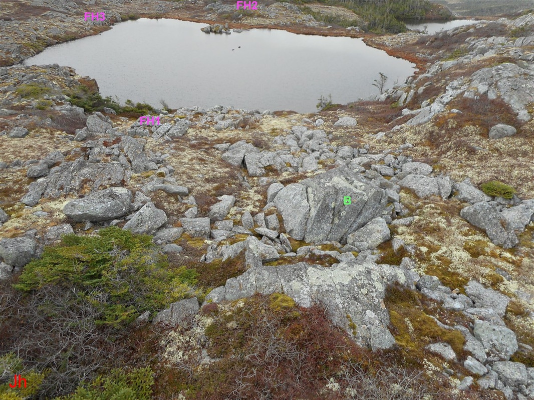
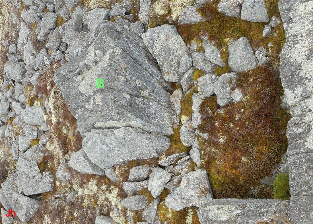
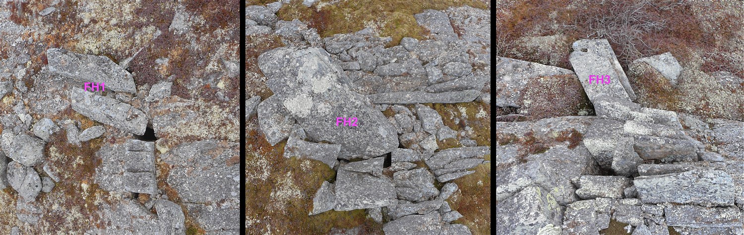
The photo above shows an aerial view of the displaced-block feature (B) and three aligned frost-heave features (FH1, FH2 and FH3) that were indicated on the previous map and are further described below. The andesite outcrops and erratics lie just to the right of the field of view shown in the photo.
Aligned frost-heave feature FH1:
Aligned frost-heave feature FH1:
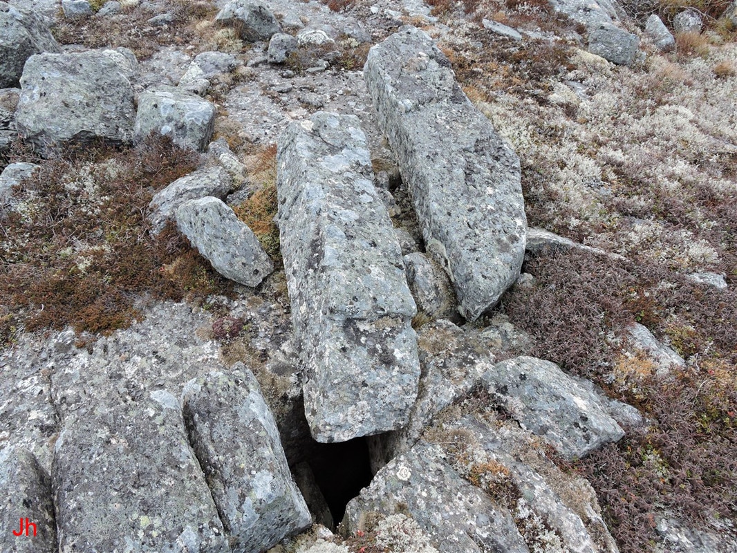
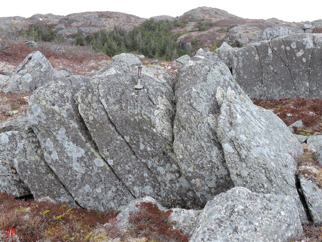
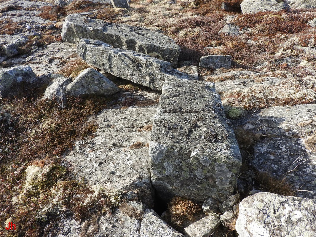
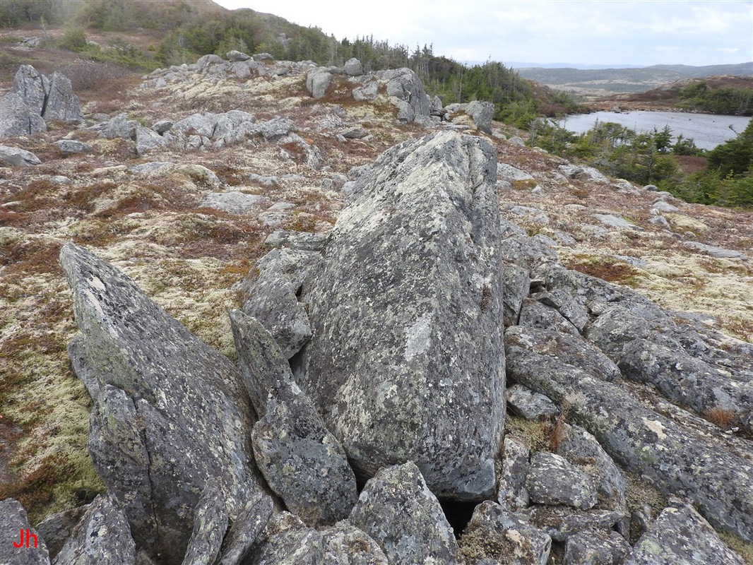
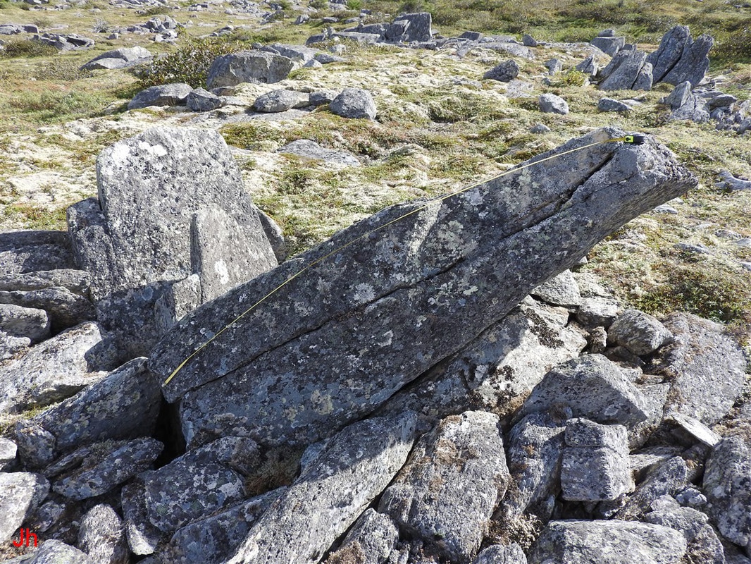
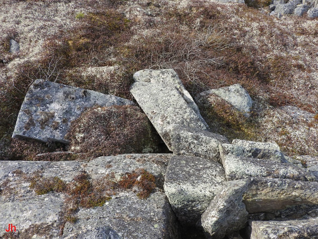
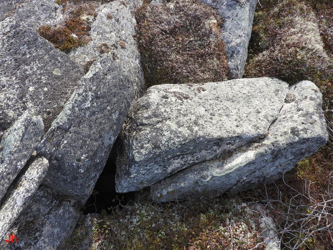
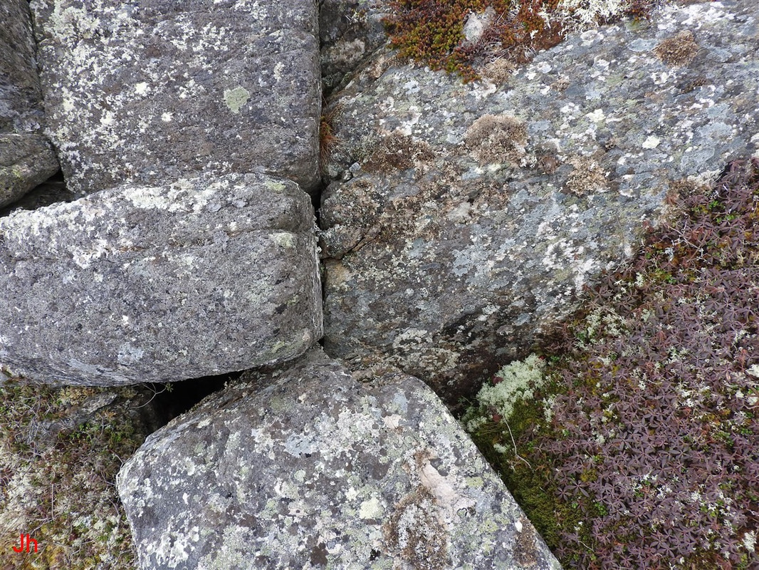
The two elongated joint blocks shown above were apparently dislodged by frost heave from the cavity appearing at the bottom center of the photograph. They then toppled to lie in their present position. The depth of the hole (measured to a debris-covered bottom) is roughly 1.4 m, while the block directly over the hole is 1.3 m long and the rightmost block is 1.6 m long. The block to the left of the hole (three sections extending straight down into the slot) is similar in overall height to the dislodged blocks (as best as could be determined) and has been raised 30 cm (height of top surface above ground level) by frost heave. The block that remains lodged in the slot also appears to have been pushed about 12 cm toward the right (as framed in photo) by ice pressure. The six photos presented below show the layout of the dislodged joint-block feature as viewed from several different angles.
|
|
The following photo shows an overhead view of the feature. This view corresponds directly with the subsequent diagram.
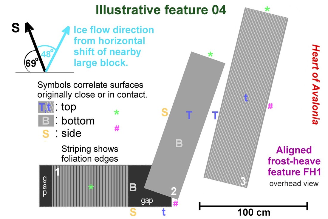
The above diagram gives a scaled representation of the dislodged blocks (2 & 3), the block (1) still in place, and the underlying cavity in the bedrock. The indicator symbols provide a guide to reconstructing the frost-heave and toppling event. As indicated on the diagram, the left side of block 3 mates with the top side of block 2. Block 2 lies with its widest face perpendicular to the ground, minimizing the height of its center of gravity. Note that the foliation in block 2 is parallel to the ground (hence not marked on the diagram), unlike in block 3, where the foliation is orthogonal to the ground. It is unclear whether the two blocks (2 & 3) were dislodged simultaneously, but this is possible. The diagram below shows a possible reconstruction of the frost heave event as it might have appeared while in progress.
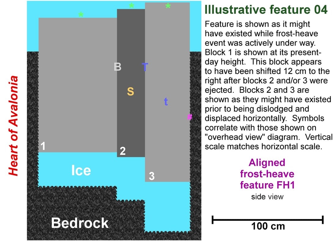
The alignment of the blocks with their long axes closely oriented along the indicated ice flow direction is critical in making the interpretation that this feature shows block alignment by ice creep as per Technical Note 07. The alignment could be coincidental but the observation that both blocks are aligned similarly helps reduce the probability of a purely chance alignment. If the two blocks were assumed to have been dislodged simultaneously while in close contact, then the possibility of a coincidental alignment rises. If the alignment of the blocks with other nearby ice flow indicators is not coincidental, then this feature (FH1) would represent an occurrence of subglacial bedrock frost heave. The photo below shows the relative indicated ice flow directions for the above feature (FH1) and the previously described ice-shifted joint-block feature (B).
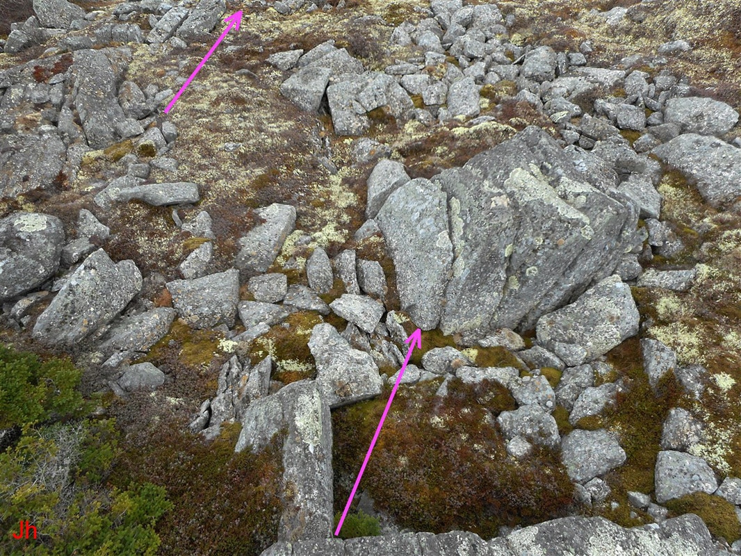
In the above photo, magenta arrows show indicated ice flow directions for joint block (B) and frost-heave feature (FH1). The feature, FH1, is hard to discern, but is visible just above and to the left of the upper magenta arrow.
Aligned frost-heave feature FH2:
Aligned frost-heave feature FH2:
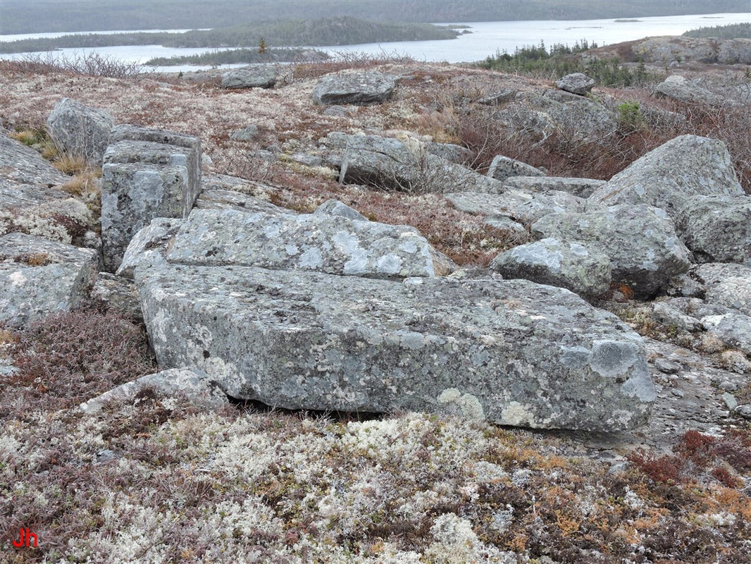
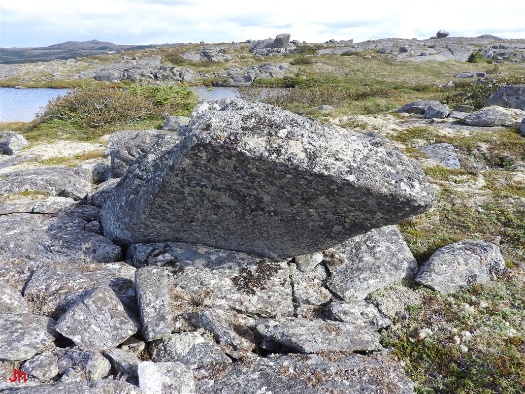
The above photo shows a large frost-heaved joint block (FH2) that has been dislodged from bedrock substrate and then toppled over to align in a direction roughly coincident with the indicated ice flow direction in the area. To the left of the large block (as framed in the photo) are smaller frost-heaved joint blocks that appear to have been displaced by lever action from the bottom of the large block. The photo below shows scale.
In the above photo, the measuring tape reads 2.1 meters. While the block is not fully dislodged, it was lifted sufficiently by frost heave to provide limited freedom to rotate about a horizontal axis. As the large block rotated, much of the bedrock around the base was displaced or broken. The pattern of disruption of the surrounding rock suggests that the rotation of the joint block was forced by surface ice loading (glacier flow) rather than only by frost heave or settling. The cavity seen at the base of the large block was measured to a depth of 1.2 m before reaching broken rock debris. The following photos show additional views of the feature, FH2, from different directions.
|
|
The direction of alignment of the elongated frost-heaved joint block (FH2) was taken to be the strike of the steeply dipping side surfaces of the block in its present tilted orientation. This alignment direction, 243 degrees true (the error in this measurement was not determined, but +/- 10 degrees might be a reasonable estimate) coincides with other indications of ice flow in the nearby area. This large block is thus a candidate for consideration as a relict subglacial frost heave event, demonstrating alignment by glacial ice creep.
Aligned frost-heave feature FH3:
Aligned frost-heave feature FH3:
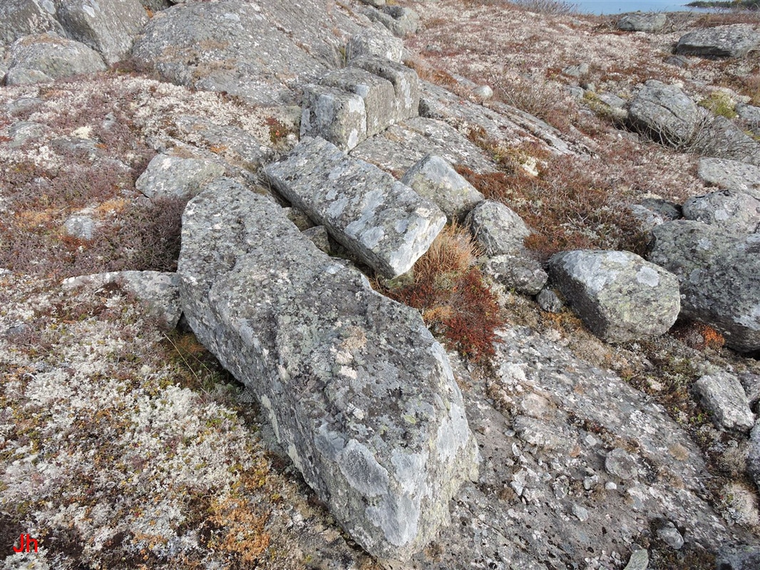
The above photo shows a pair of joint blocks (FH3) at the bottom of a low, sloping bedrock outcrop. The width of the top block is 70 cm. The blocks were displaced upward, then outward from the sloping bedrock surface by frost heave. Frost heave action is also evident in the joint blocks above the dislodged blocks, but these blocks were not free to rotate about a horizontal axis. The larger joint block lying at the bottom of the slope just left of the dislodged blocks might also have originated via frost heave from the slope seen in the picture. However, because this block was partially buried in peat and vegetation, it was not possible to reconstruct its displacement. The two photos below show closeups of the blocks (FH3) viewed from the bottom of the slope.
|
|
The second (right) photo above shows the back end of the top block (FH3) and illustrates the rotation of the block about a horizontal axis. Note that this dislodged and rotated joint-block feature closely resembles aligned joint-block occurrences described in Illustrative feature 03, under the heading "Analysis of the plucked area". The direction of alignment of the blocks (FH3) was determined by measuring the strike of their edges, as was done for the block FH2. The strike measurement was performed by sighting along the edges of the blocks while walking away from them carrying a GPS unit. Course-made-good on a map of the GPS track was taken to be the strike. However, because the blocks were short in this instance, and situated between an obscuring slope and a lake, the measurement error for this feature was undoubtedly larger than for FH2, although the error was not determined. An alternate means for assessing relative alignments of FH3 and the other aligned features in the area, using bedrock foliation as a reference, is illustrated below.
Comparison of block shifts and alignments using bedrock foliation as a reference:
Comparison of block shifts and alignments using bedrock foliation as a reference:
The four overhead photos shown above are all oriented with longitudinal foliation in the bedrock running roughly parallel to the bottoms of the frames. The tops of the frames lie toward the west, while the left sides of the frames lie toward the south. The longitudinal foliation in the generally schistose bedrock showed a fairly consistent strike of about 21 degrees true in the area of the observed features. Indicated directions of alignment or shift as depicted on the photos is affected by camera perspective. The pictures were not taken along a line of sight exactly orthogonal to the ground nor were they taken from an altitude greatly exceeding the heights of the features. A long pole, not a drone, was used for camera positioning.
Validity of subglacial frost-heave interpretation:
If the aligned features described above are not aligned with each other simply by chance (the coincidence would also need to include the andesite outcrops and erratics discussed previously) then the action of a glacier is implied in guiding the alignments of the dislodged frost-heaved bedrock occurrences. There are two potential problems in reaching the conclusion that chance was not responsible for the observations. Firstly, the sample size was small. Secondly, the possibility of selection bias exists in that appropriately-aligned dislodged frost-heave features might tend to stand out and be preferentially noticed. The cause of the small sample size was the failure to identify any more dislodged, elongated frost-heave specimens in the local area. Most of the observed loose joint blocks did not lie recognizably close to their points of origin. Selection bias was a lesser problem because the pool of samples available for selection was so small.
Including bedrock frost heave specimens that were still rooted in substrate would provide a much larger sample size. This type of frost-heave occurrence was difficult to analyze since, usually, there was no clear indication of horizontal shift in these specimens. However, in specimens where ice loading seemingly tilted or otherwise shifted a frost-heaved block still anchored in bedrock, the tilts or shifts appeared strongly biased in favor of the specimens being pushed in a southerly and/or westerly direction (down-ice). The above assertion is based on anecdotal evidence. No statistical analysis of this type of occurrence was undertaken. The lack of good statistics supporting the glacial-creep alignment theory weakens the conclusion that IF04 demonstrates subglacial bedrock frost heave. However, rejecting the conclusion would necessitate postulating an alternative explanation for horizontal displacements and rotations of dislodged frost-heaved blocks. Taken in conjunction with IF01, IF02 and IF03, this illustrative feature adds further weight to the concept of a subglacial origin for certain bedrock frost-heave instances.
Nearby examples of ice-disrupted bedrock:
The area where the above-described frost-heave and other features were located comprises one of the densest accumulations of disrupted-bedrock features on the Isthmus of Avalon. The area also includes some of the largest individual frost heaved monoliths observed on the Isthmus. Some examples demonstrating the unusual severity of local bedrock disruption are shown below.
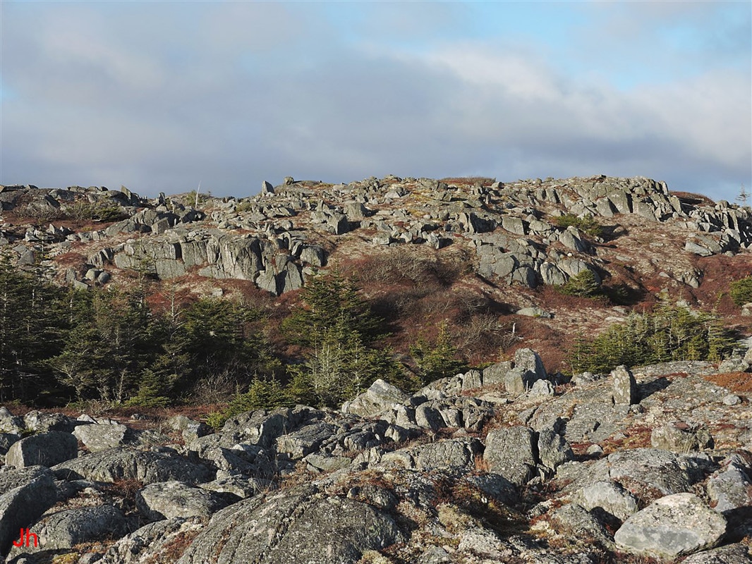
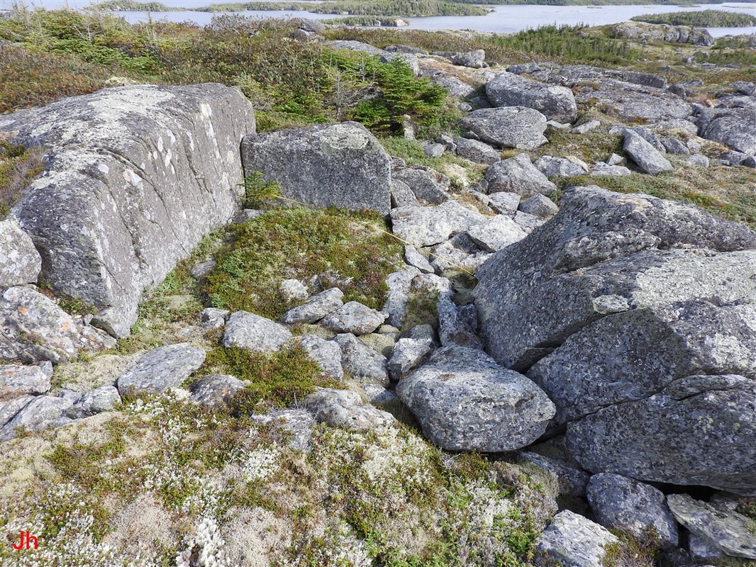
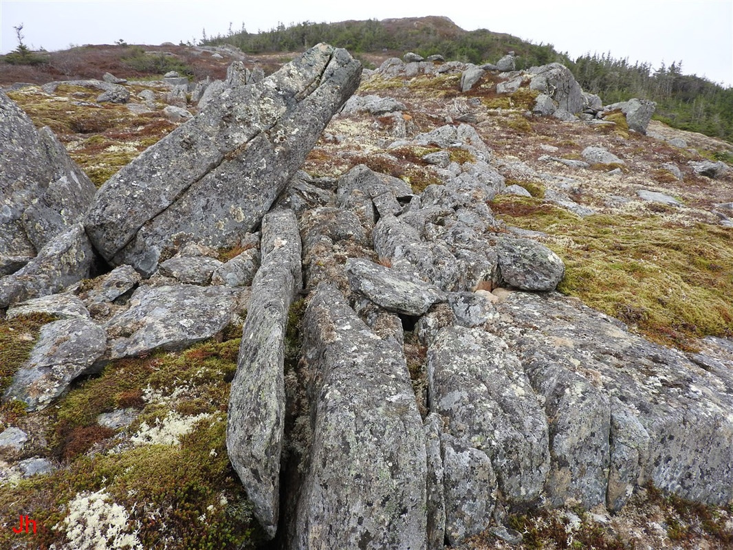
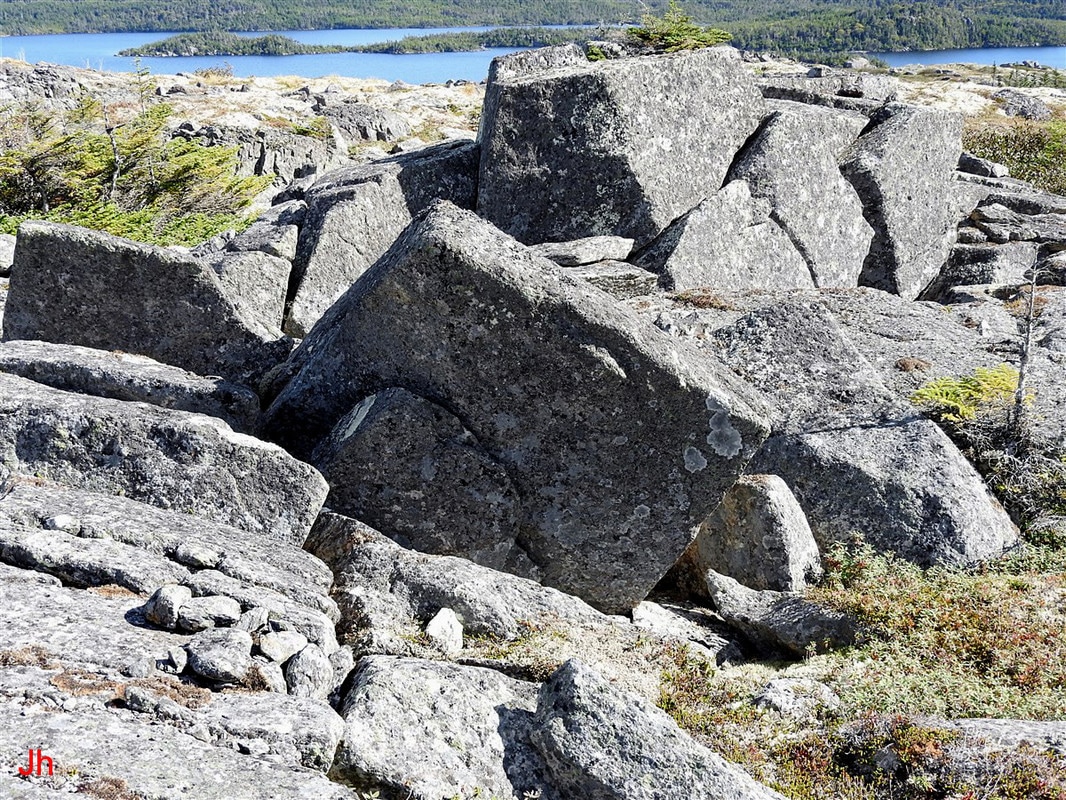
The photo above shows what looks like a felsenmeer or blockfield located about 100 m south of the IF04 area. Most of the jagged and broken rock visible in the photo is frost-heaved bedrock still rooted in substrate. The bedrock contains abundant widened joints, fissures and sharp-angled failure planes. On cursory examination, the pictured area resembles a scene of intense periglacial activity where thermally-induced frost wedging shattered the bedrock. A closer look reveals an asymmetry in the bedrock disruption that is hard to explain within the context of the periglacial-origin model. The asymmetry is particularly apparent when noting instances of bedrock disruption occurring on southwesterly facing slopes. Small cliffs or slopes, often only a meter or two high, are frequently "plucked" when facing south or west, but left intact when facing north or east. There is much additional evidence of limited ice flow across the scene illustrated above. The ice flow shifted the rocks only a small amount, but with indications of powerful directed ice loading.
Both of the above-pictured frost-heave features lie close to the lake centering the map area (see map near the beginning of this section) for IF04. The monoliths, both over 1.5 meters high are also illustrated and described in the section Frost-heaved monoliths: Examples(1) and are included here only to link them to the possibility that they are of subglacial origin.
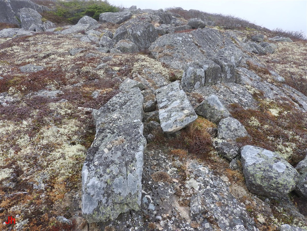
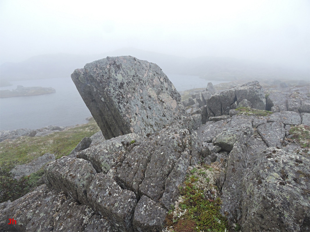
This large (top of horizontal central block about 1.5 m above ground level) group of frost-heaved blocks lies within the IF04 map area. A more detailed description and set of images for this feature is found in the section Frost-heaved monoliths: Examples(1). The above photo was taken from an angle highlighting a pair (one is in front of the other) of large (2.4 m long) tilted frost-heaved joint blocks (foreground, center of photo) that lean toward the southwest (ice flow direction). This pair of blocks was not fully dislodged, but nevertheless provided a further indication of interaction between a frost heave process and an overlying moving glacier.
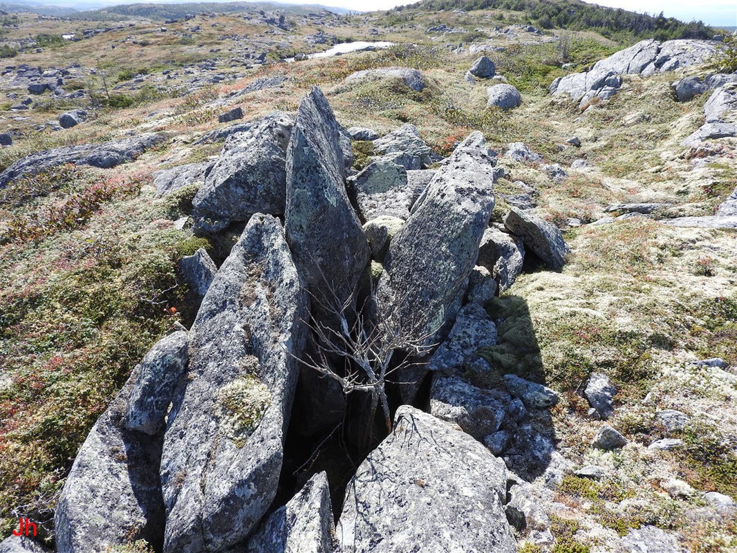
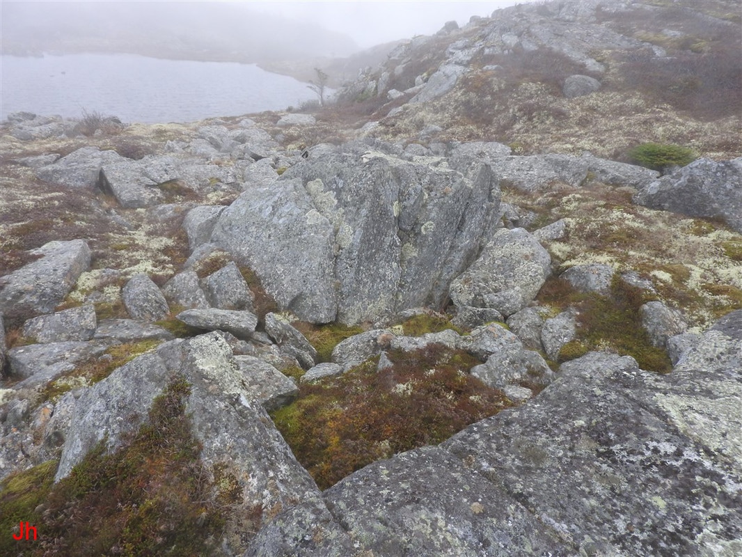
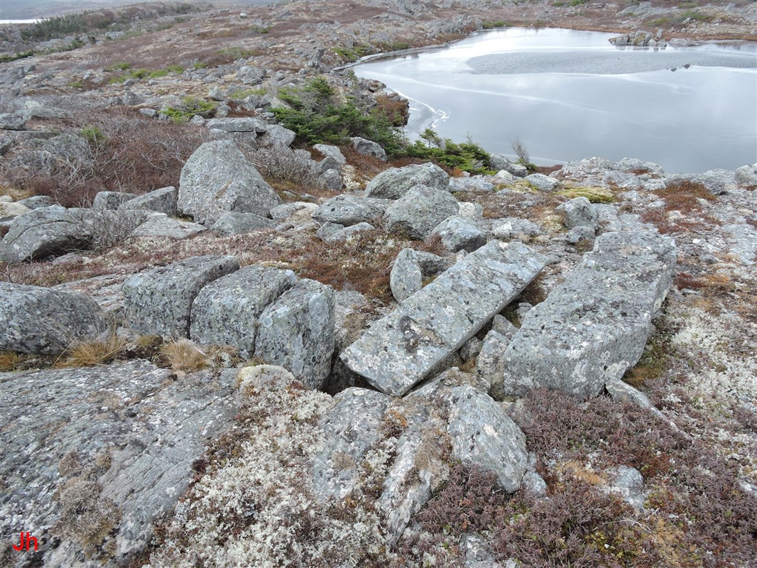
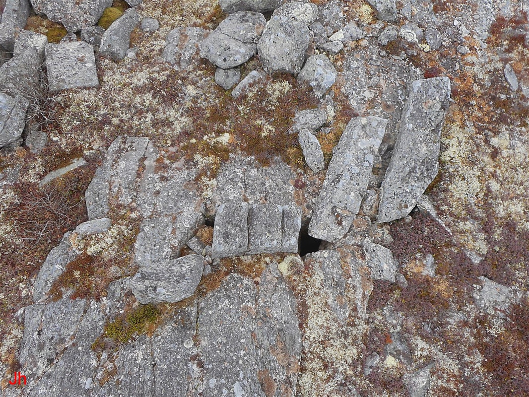
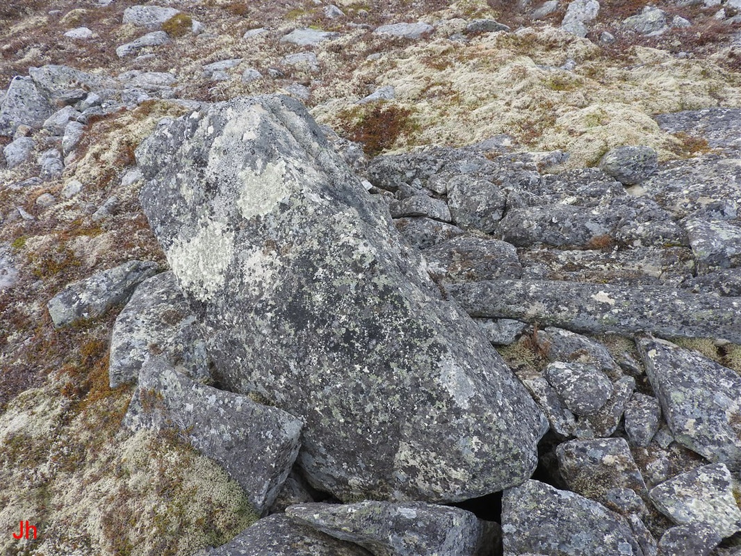
The above photo shows a large disrupted-bedrock feature viewed from the north, looking south. This feature is located close to the previously described features, shifted block (B) and aligned frost-heaved joint block (FH1). The tallest fragment (center left, toward back) extends about 1 meter above ground level. The fissure at the center of the feature is more than 1.7 meters deep. It is difficult to reconstruct this frost-heave occurrence because the bedrock has been so severely disturbed. Nevertheless, it seems likely that the two large upright fragments seen at the rear of the field of view originated in what is now the cavity, and were then shifted southward. Features like this, with significant voids in the bedrock open to the surface, are suggestive of frost-heave action in an environment where water/ice is retained at the surface under pressure. A cold-based subglacial environment would meet this requirement. There are several similar open bedrock frost-heave features in the neighborhood of IF04.
|
|
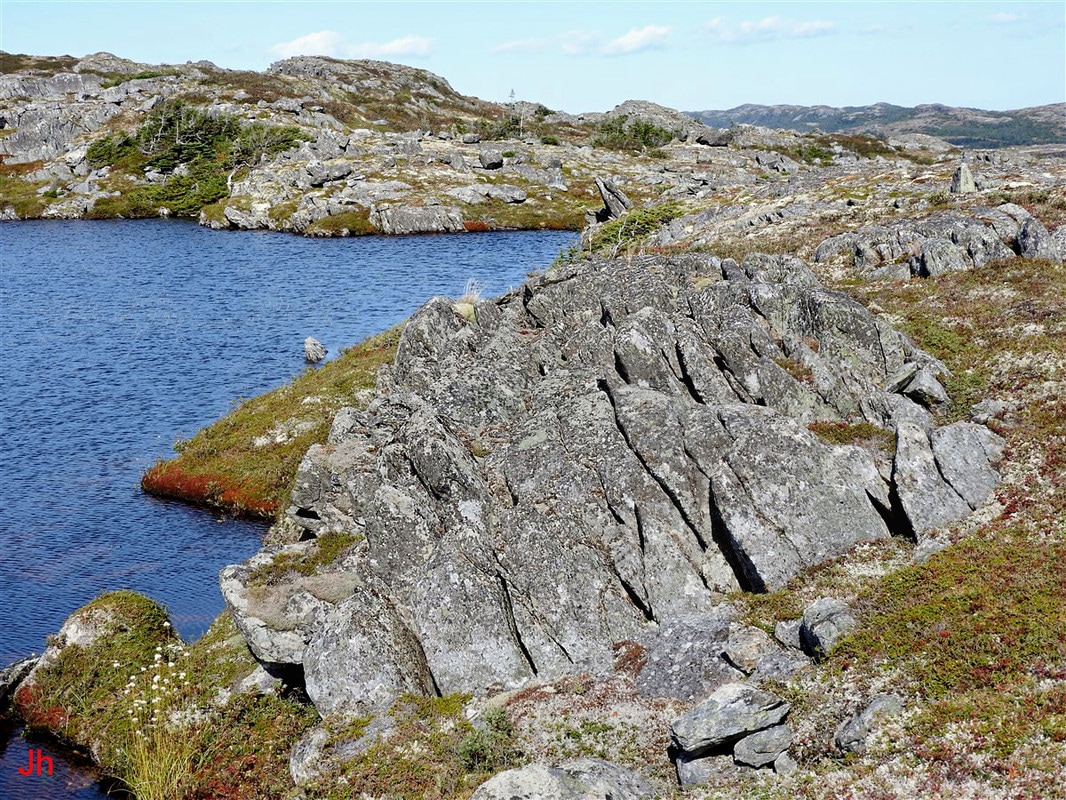
The two photos above show a sloping oval-shaped outcrop of ice-disrupted bedrock in the IF04 map area. The outcrop is about 13 meters long from the foreground edge to the background edge. Viewed from an oblique overhead angle (both photos look north) the second picture reveals a consistent westerly (down-slope) tilt in the assembly of frost-shifted joint blocks. In certain respects this feature provides an example of restricted plucking, that is, plucking where no rock is actually transported away from the site. In other respects, it resembles a closely spaced assembly of frost-heaved monoliths.
There are three possible explanations for the tilt of the blocks:
1) The foliation in the bedrock dips non-vertically, with the angle of dip inclined in the direction of the tilt.
2) The blocks tilted westward because there was more room for them to move in the down-slope direction.
3) The blocks were pushed in a westerly direction by ice loading from an overlying glacier moving in a southwesterly direction.
Explanation (1) appears plausible because so much of the bedrock in the area is frost-heaved and many of the frost-heaved blocks lean westward. However, there are several nearby examples of fissures and failure surfaces following longitudinal cleavage where the dip of the cleavage is approximately vertical. The tilt of the blocks in the above-illustrated group changes from nearly vertical at the back (east) edge of the group to almost horizontal at the down-slope (west) edge. At most, non-vertically dipping cleavage appears to play a minor role in determining the tilt of the displaced blocks.
Explanation (2) is clearly appropriate. The type of frost-heave (restricted plucking) seen above is opportunistic, with rock shifting along the path of least resistance. There would be no need to seek a further explanation for the consistent tilt if features such the one shown above were equally abundant on east-descending slopes. This does not conform with observations. There are very few examples of restricted plucking on east-descending slopes in the neighborhood of IF04, and the few examples that are observed are very limited in size. Alternatively, frost-wedged hillside (restricted plucking) features on west-descending slopes are abundant and often large in scale. This unmistakable asymmetry is key to demonstrating the action of glacial ice flow in guiding the formation of the frost-wedged hillside features.
Explanation (3) is appropriate in light of the asymmetry of occurrence of the frost-wedged hillside features as discussed above. This explanation leads directly to the subglacial bedrock frost heave model, at least for the numerous blocks in the above assembly that were displaced mainly upward.
The feature shown above indicates a significant linkage between the two most prevalent bedrock frost heave features in the vicinity of IF04. Specifically, bedrock frost heave and hillside frost wedging (restricted plucking) are closely linked in the above-described outcrop and could therefore represent two aspects of the same phenomenon. If hillside frost wedging in the area around IF04 can be shown to be of identical origin as nearby and closely associated bedrock frost heave, then the subglacial frost heave model becomes supported by the asymmetry of occurrence of frost-wedged hillsides.